Holder for variable sizes of tools and implements

a tool and variable technology, applied in the field of accessories for securing and storing objects, can solve the problems of lack of versatility of known devices, inability to fit objects much larger in diameter or heavier, such as baseball bats, in the clip or fastener, etc., and achieve the effect of enhancing the gripping pressure on the object and high friction coefficien

Inactive Publication Date: 2012-03-01
STOCK DANIEL F
View PDF10 Cites 18 Cited by
  • Summary
  • Abstract
  • Description
  • Claims
  • Application Information

AI Technical Summary

Benefits of technology

[0006]A holder for securing objects comprising a base plate for securing to a surface and a pair of opposed grippers rotatably mounted on the plate. The grippers are mirror images of each other and configured having a body, a heel, an upwardly arcing nose section opposite the heel with a curved or arcuate gripping surface between the heel and the nose. The grippers are biased toward each other such that noses abut each other when there is no object between the grippers. The grippers are formed from rubber having a relatively high coefficient of friction. The gripping surface can have scoring or grooves. An object to be secured is inserted up between the grippers and the grippers rotate apart to accommodate the object between the gripping surfaces. The biasing means, for example a spring, biases the grippers towards each other to secure the object between the grippers. The downward force of the object between the grippers draws the grippers toward each other to enhance the gripping pressure on the object.

Problems solved by technology

In any event, these known devices lack versatility since the fasteners or clips are sized to accommodate the most common of tools or other objects.
Objects that are much larger in diameter or heavier, such as a baseball bat, will not fit in the clip or fastener.

Method used


Image

  • Holder for variable sizes of tools and implements
  • Holder for variable sizes of tools and implements
  • Holder for variable sizes of tools and implements

Examples


Embodiment Construction

[0013]The following is a detailed description of an embodiment of an easy open picture frame representing the best mode of working the invention presently known by the inventor.

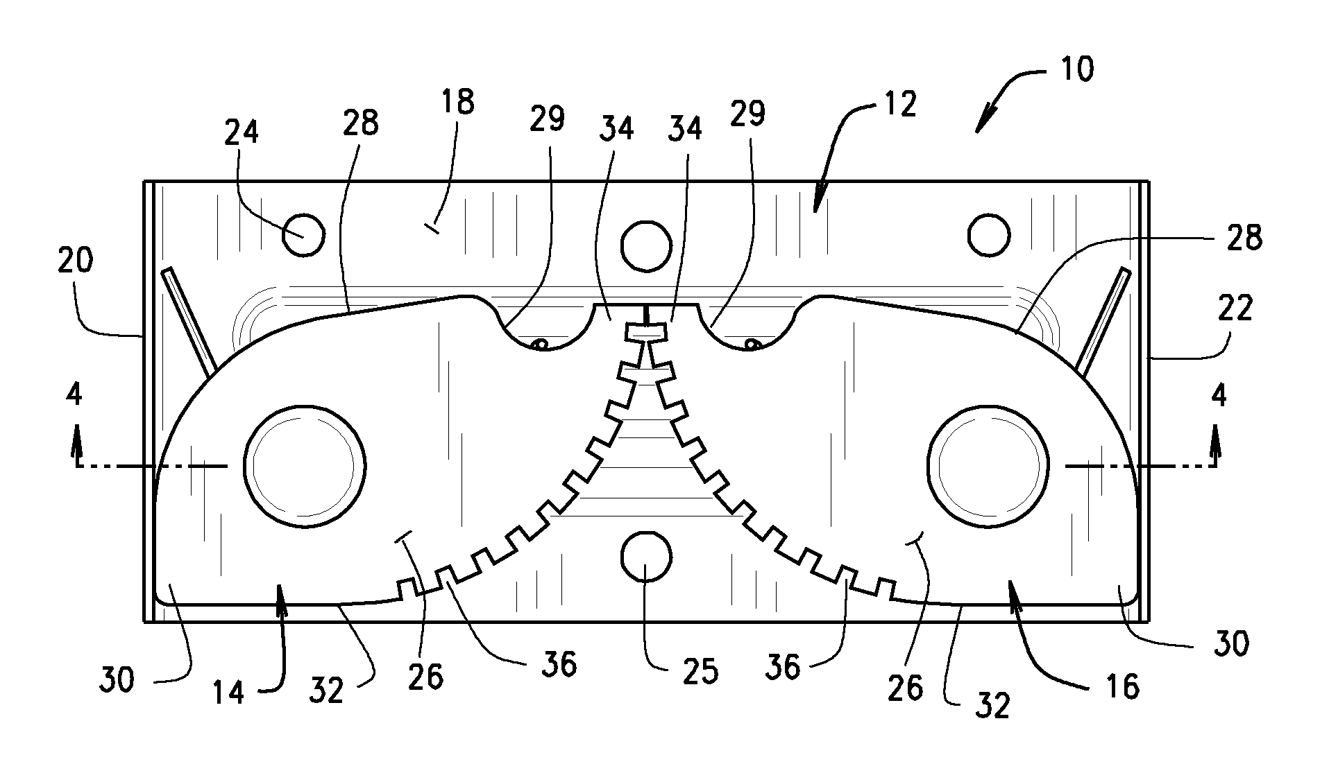
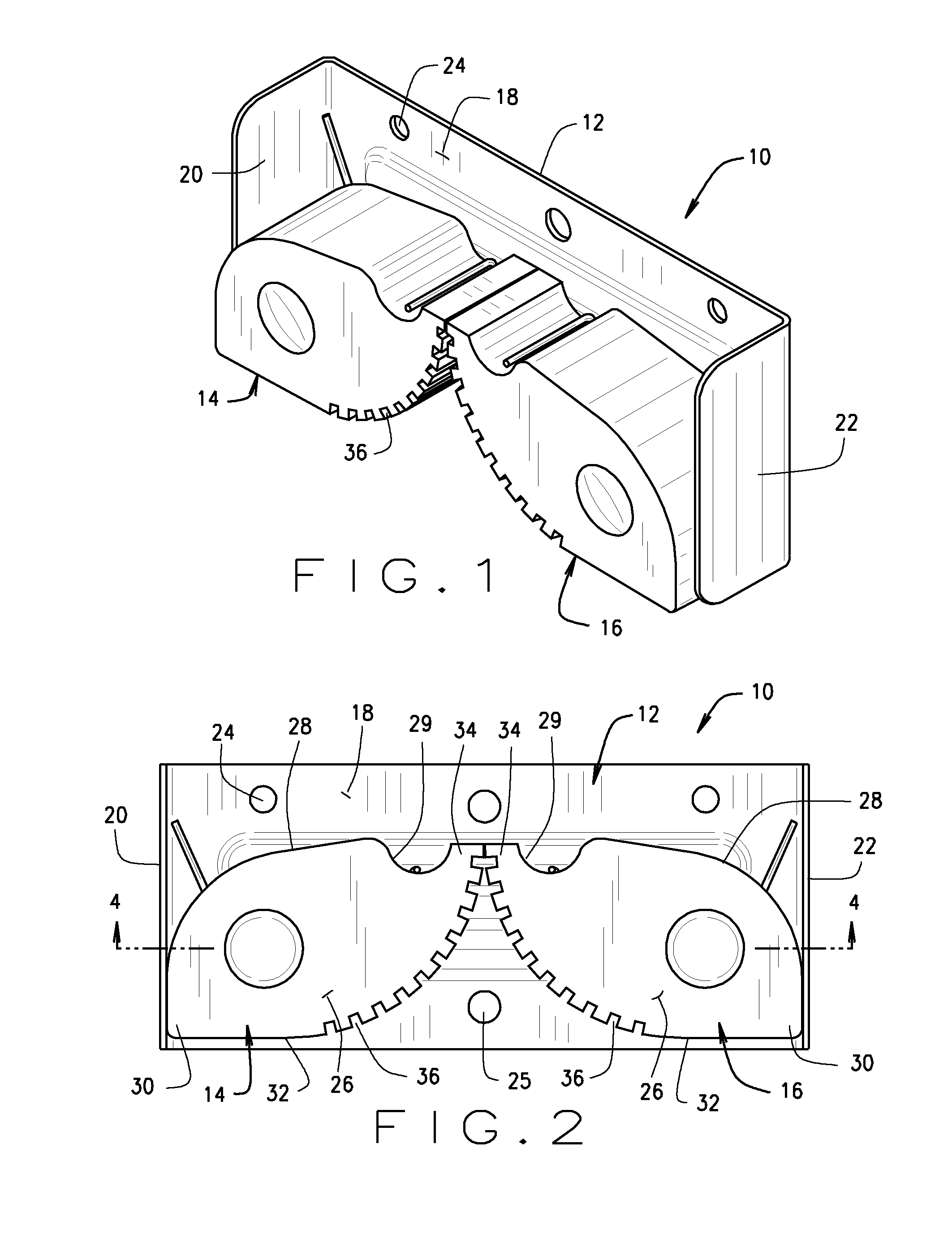
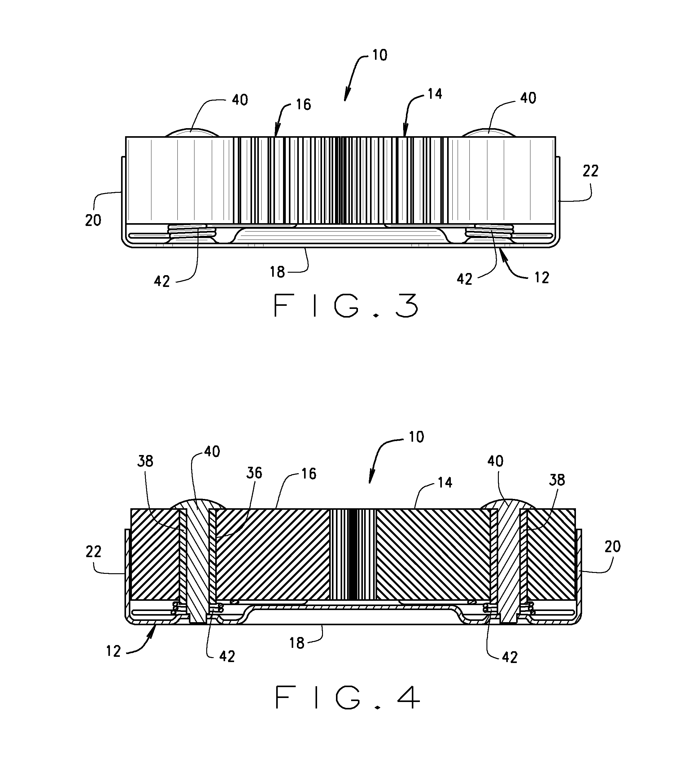
[0014]The holder of the present invention is indicated generally be reference numeral 10 in the various drawings. Holder 10, as shown, has a base 12, a first gripping or securing element referred to as a gripper 14 and a second, opposed gripper 16.

[0015]Base 12, as shown, has a relatively elongated, substantially flat body 18 with a first end wall 20 at one end of the body and a second end wall 22 at the second end of the body and can be referred to as base, a base plate or just a plate. However, any acceptable structure can function as a base and it does not need to be configured as a plate. In the illustrated base the two end walls are orientated at right angles to the body. The two end walls can be a party of body 18 bent into this perpendicular configuration or can be separate elements fixed to the body b...


PUM

PropertyMeasurementUnit
biasing forceaaaaaaaaaa
coefficient of frictionaaaaaaaaaa
magnetic structureaaaaaaaaaa

Abstract

A holder for securing objects having a plate for securing to a surface and a pair of opposed grippers rotatably mounted on the plate. The grippers are mirror images of each other and configured with a body, a heel on the butt end of the body and an upwardly arcing nose on the body opposite the heel with a curved gripping surface extending between the heel and the nose. The grippers are biased toward each other such that noses abut each other when there is no object between the grippers. An object to be secured is inserted between the grippers and the grippers rotate apart to accommodate the object and the biasing spring urges the grippers towards each other to secure the object between the grippers.

Description

CROSS-REFERENCE TO RELATED APPLICATIONS[0001]This application claims the benefit of provisional application Ser. No. 61 / 378.573, filed Aug. 31, 2010, which is incorporated herein by reference.STATEMENT REGARDING FEDERALLY SPONSORED RESEARCH OR DEVELOPMENT[0002]Not applicable.BACKGROUND OF THE INVENTION[0003]The invention relates generally to apparatus for securing and storing objects, such as tools or other implements, and more particularly to an apparatus or holder that can be attached or mounted on a surface and employs rotatable grippers to secure tools or other implements of variable sizes ranging from very thin or narrow like a fishing rod to more substantial such as shovel or baseball bat.[0004]Holders for securing and storing objects such as tools are well known. For example, holders that mount to a surface, such as a wall, and accommodate one or more tools or other implements are known. In general, such devices include a base, which is generally flat and elongated, that is a...

Claims


Application Information

Patent Timeline
Patent Type & Authority Applications(United States)
IPC IPC(8): F16M13/02F16B2/10H01F7/02F16M13/00
CPCF16B2/10B25H3/04
Inventor STOCK, DANIEL F.
Owner STOCK DANIEL F
Why Eureka
Try Eureka