Radiographic imaging device
a radiographic imaging and imaging device technology, applied in the direction of radiographic control devices, instruments, television systems, etc., can solve the problems of late timing of detecting the start of radiation radiation radiation, noise at the radiation detecting element, etc., to achieve accurate radiation detection and suppress the effect of nois
- Summary
- Abstract
- Description
- Claims
- Application Information
AI Technical Summary
Benefits of technology
Problems solved by technology
Method used
Image

Examples
first exemplary embodiment
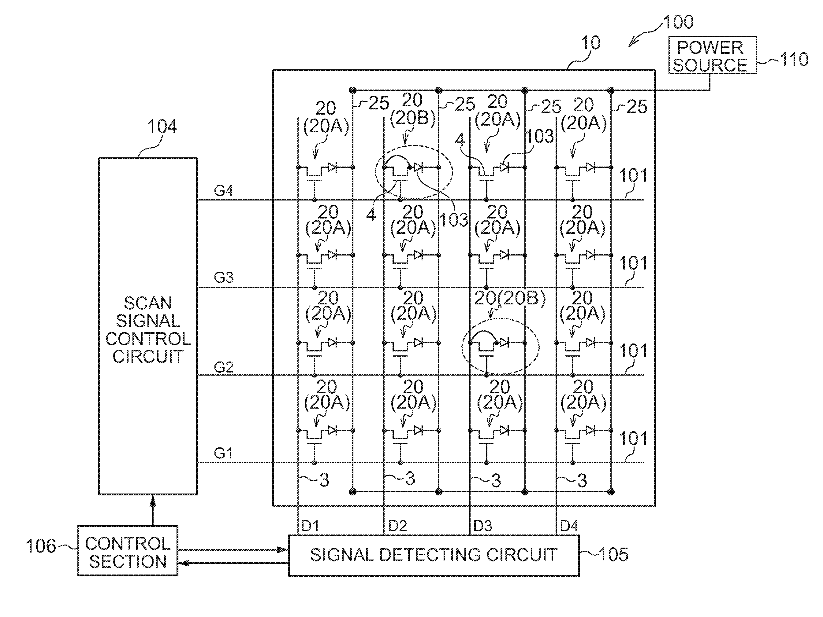
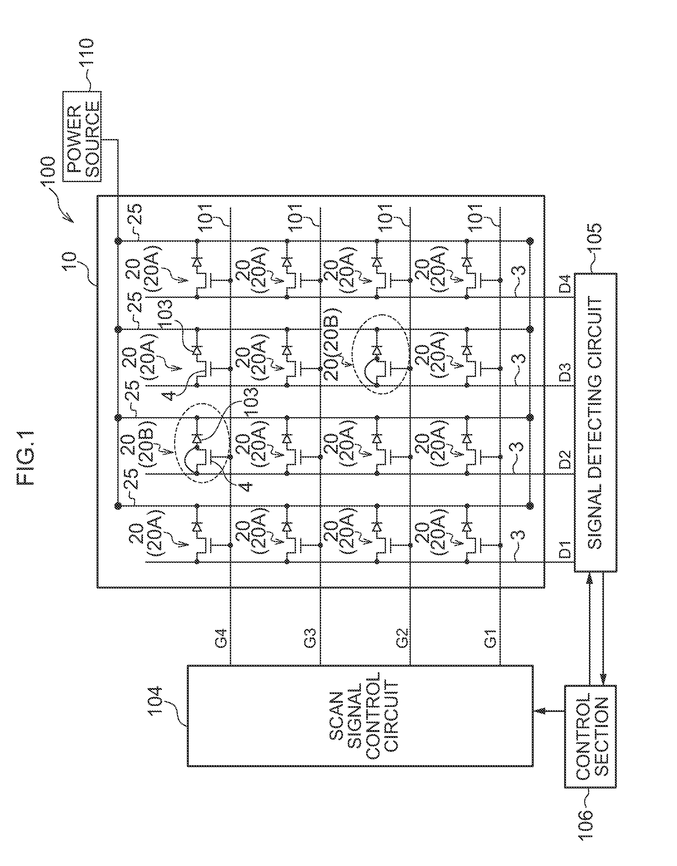
[0062]The schematic configuration of a radiographic imaging device 100 that uses the radiation detecting element 10 relating to the first exemplary embodiment is shown in FIG. 1.
[0063]As shown in FIG. 1, the radiographic imaging device 100 relating to the present exemplary embodiment has the indirect-conversion-type radiation detecting element 10. Note that the scintillator that converts radiation into light is omitted.
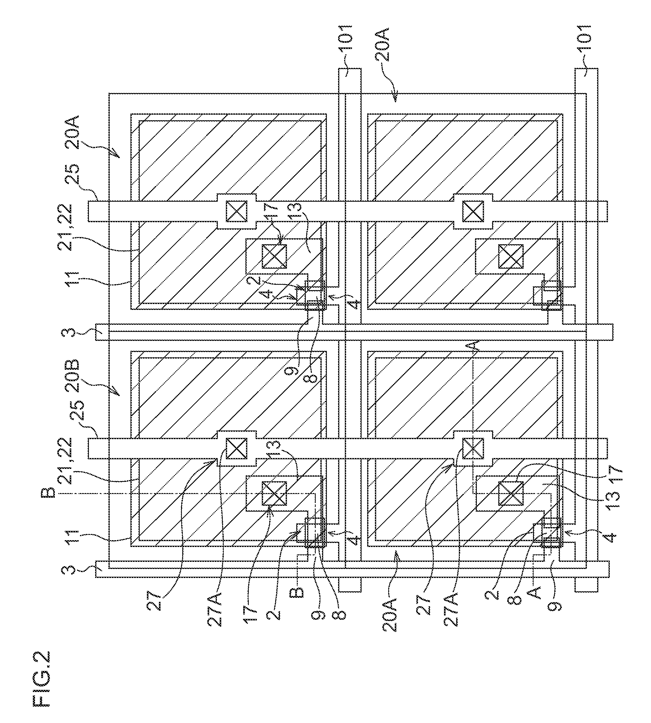
[0064]Plural pixels 20 are disposed at the radiation detecting element 10. The pixel 20 has a sensor portion 103 that receives light, generates charges, and accumulates the generated charges, and a TFT switch 4 for reading-out the charges accumulated in the sensor portion 103. In the present exemplary embodiment, charges are generated at the sensor portions 103 due to light, that has been converted by the scintillator, being illuminated onto the sensor portions 103.
[0065]The plural pixels 20 are disposed in the form of a matrix in one direction (the lateral direction ...
second exemplary embodiment
[0125]A second exemplary embodiment is described next.
[0126]The overall configuration of the radiographic imaging device 100 that uses the radiation detecting element 10 relating to the second exemplary embodiment is shown in FIG. 11. Note that portions that are the same as in the above-described first exemplary embodiment (see FIG. 1) are denoted by the same reference numerals, and description thereof is omitted.
[0127]In the radiation detecting element 10 relating to the second exemplary embodiment, scan lines 108 are provided in parallel to the scan lines 101 at the lines of pixels in one direction (the lateral direction in FIG. 11, hereinafter also called “row direction”) at which the radiation detection pixels 20B are provided. Hereinafter, in the present exemplary embodiment, in order to distinguish between the scan lines 101 and the scan lines 108, the scan lines 101 are called the first scan lines 101, and the scan lines 108 are called the second scan lines 108.
[0128]Of the p...
third exemplary embodiment
[0144]A third exemplary embodiment is described next.
[0145]The overall configuration of the radiographic imaging device 100 that uses the radiation detecting element 10 relating to the third exemplary embodiment is shown in FIG. 16. Note that portions that are the same as in the above-described first exemplary embodiment (see FIG. 1) are denoted by the same reference numerals, and description thereof is omitted.
[0146]In the radiation detecting element 10 relating to the third exemplary embodiment, lines 121 for radiation detection are provided in parallel to the scan lines 101 at the lines of pixels in one direction (the lateral direction in FIG. 16, hereinafter also called “row direction”) at which the radiation detection pixels 20B are provided. Further, lines 122 for noise detection are provided at the lines of pixels that are adjacent to the respective lines of pixels in the row direction at which the lines 121 for radiation detection are provided.
[0147]Among the plural pixels 2...
PUM
 Abstract
Description
Claims
Application Information
 - R&D
- Intellectual Property
- Life Sciences
- Materials
- Tech Scout
- Unparalleled Data Quality
- Higher Quality Content
- 60% Fewer Hallucinations
Browse by: Latest US Patents, China's latest patents, Technical Efficacy Thesaurus, Application Domain, Technology Topic, Popular Technical Reports.
© 2025 PatSnap. All rights reserved.Legal|Privacy policy|Modern Slavery Act Transparency Statement|Sitemap|About US| Contact US: help@patsnap.com