
Integrated charging device for electric vehicle

a charging device and electric vehicle technology, applied in the direction of battery/fuel cell control arrangement, transportation and packaging, propulsion by batteries/cells, etc., can solve the problems of increased installation cost and maintenance cost, complicated structure of the entire system,

Inactive Publication Date: 2012-03-01
SAMSUNG ELECTRO MECHANICS CO LTD
View PDF4 Cites 59 Cited by
  • Summary
  • Abstract
  • Description
  • Claims
  • Application Information

AI Technical Summary

Benefits of technology

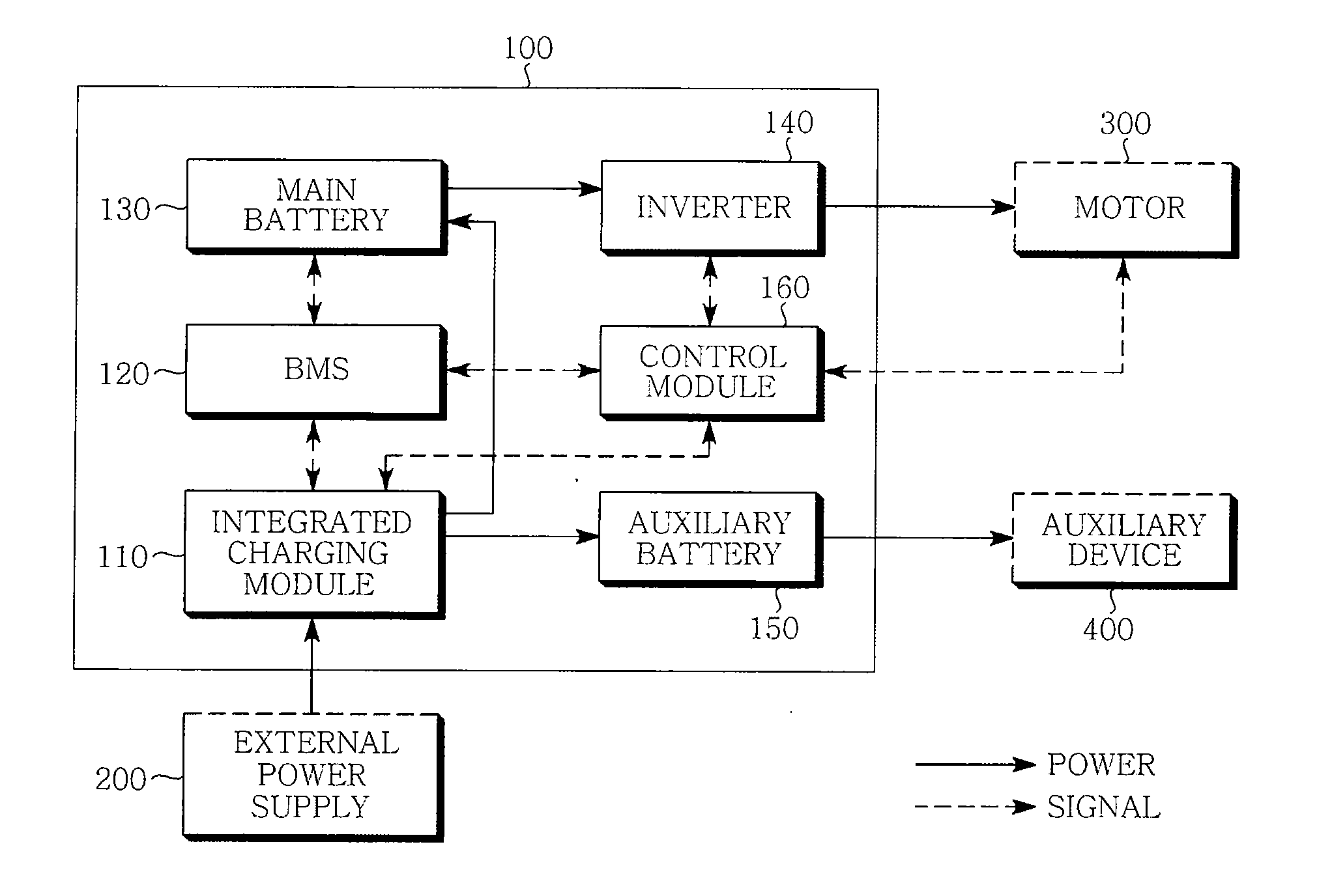
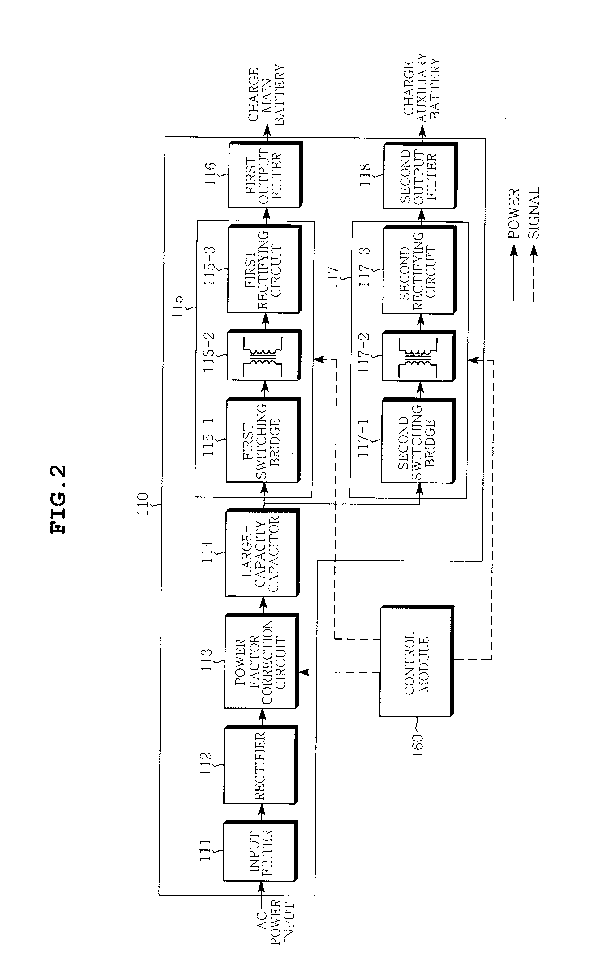
[0013]The integrated charging module may include: an input filter removing high frequency noise of the AC power input from the external power supply; a rectifier rectifying the AC power from which the noise is removed and converting it into the DC power; a power factor correction circuit correcting power factor of the converted DC power; a large-capacity capacitor smoothing the DC power of which power factor is corrected; a DC / DC converter for a main battery converting the smoothed DC power into the boosted or reduced first DC voltage to be charged in the main battery; and a DC / DC converter for an auxiliary battery converting the smoothed DC power into the boosted or reduced second DC voltage to be charged in the auxiliary battery.
[0014]The integrated charging module may further include: a first output filter removing noise of the DC power output from the DC / DC converter for the main battery; and a second output filter removing noise of the DC power output from the DC / DC converter for the auxiliary battery.
[0018]The control module may control the amount of power output from the converted AC power to allow the first transformer to boost or reduce the converted AC power according to the capacity of the main battery.

Problems solved by technology

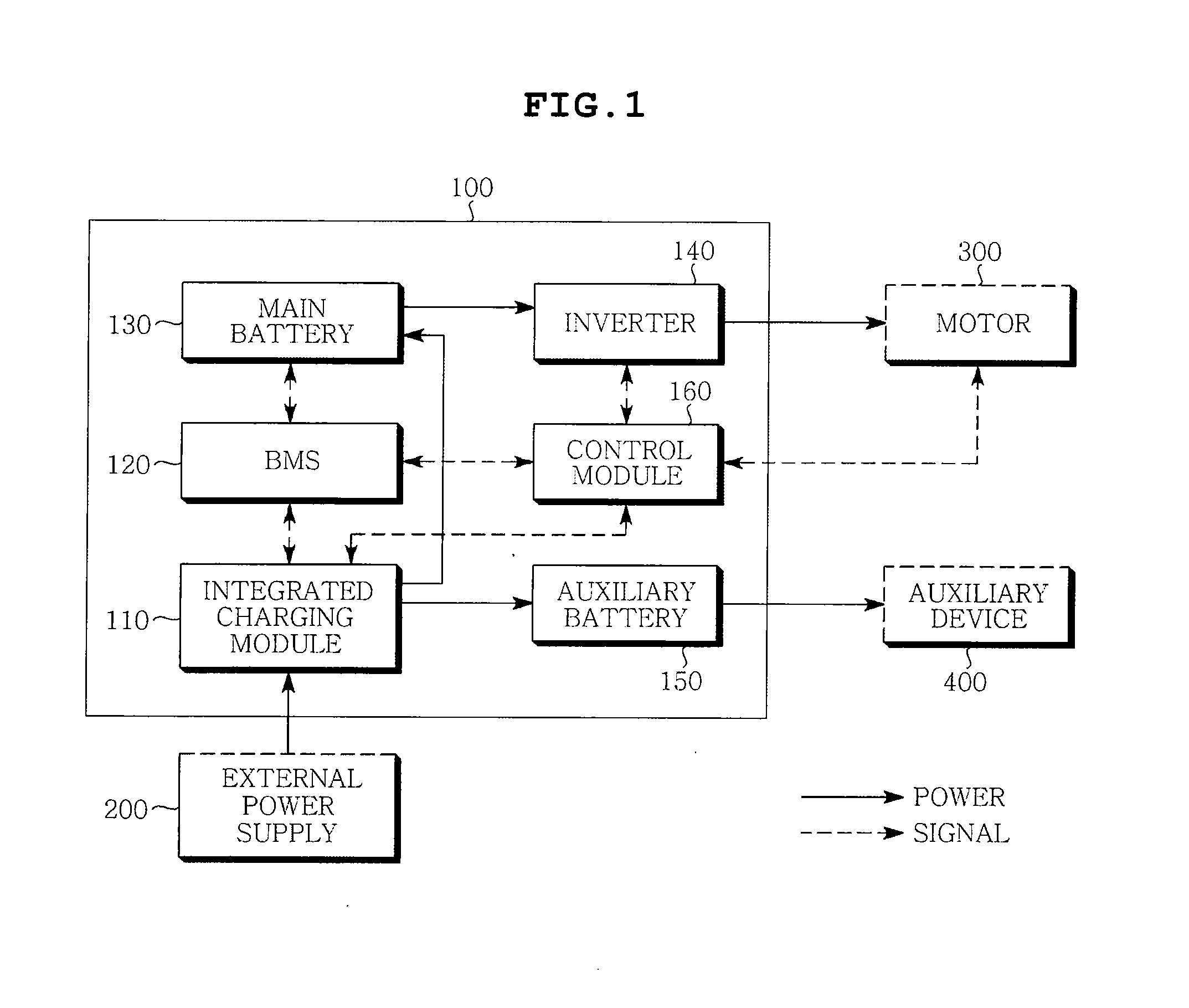
However, the charger for the electric vehicle according to a prior art occupies a large space in the vehicle since the secondary battery (main battery) for the power supply for driving the vehicle and the secondary battery (auxiliary battery) for the auxiliary power supply are each provided as a separate module.
In addition, the structure of the entire system is complicated and the weight thereof is increased since a separate cooling system for each module is needed, such that the installation cost and the maintenance cost are increased.

Method used


Image

  • Integrated charging device for electric vehicle
  • Integrated charging device for electric vehicle
  • Integrated charging device for electric vehicle

Examples


Embodiment Construction

[0022]Various objects, advantages and features of the invention will become apparent from the following description of embodiments with reference to the accompanying drawings.

[0023]The terms and words used in the present specification and claims should not be interpreted as being limited to typical meanings or dictionary definitions, but should be interpreted as having meanings and concepts relevant to the technical scope of the present invention based on the rule according to which an inventor can appropriately define the concept of the term to describe most appropriately the best method he or she knows for carrying out the invention.

[0024]The above and other objects, features and advantages of the present invention will be more clearly understood from the following detailed description taken in conjunction with the accompanying drawings. In the specification, in adding reference numerals to components throughout the drawings, it is to be noted that like reference numerals designat...


PUM


Abstract

Disclosed herein is an integrated charging module device for an electric vehicle. The integrated charging module device for an electric device includes: a main battery supplying power for driving an electric vehicle; an auxiliary battery supplying power for driving an auxiliary device within the electric vehicle; an integrated charging module converting external power into a first DC voltage to be charged in the main battery and a second DC voltage to be charged in the auxiliary battery; and a control module controlling the charging of the main battery and the auxiliary battery. The present invention includes the integrated charging modules for charging the main battery and the secondary battery, thereby making it possible to increase the efficiency of the spatial arrangement in a vehicle and simplifying the cooling system.

Description

CROSS REFERENCE TO RELATED APPLICATION[0001]This application claims the benefit of Korean Patent Application No. 10-2010-0084225, filed on Aug. 30, 2010, entitled “Integrated Charging Device For Electric Vehicle,” which is hereby incorporated by reference in its entirety into this application.BACKGROUND OF THE INVENTION[0002]1. Technical Field[0003]The present invention relates to an integrated charging device for an electric vehicle.[0004]2. Description of the Related Art[0005]Generally, an electric vehicle (EV) includes a secondary battery (main battery) for a power supply for driving a vehicle used as a driving source of a driving motor for driving a vehicle. The secondary battery (main battery) for a power supply for driving a vehicle is an on-board charger that is mounted in the vehicle to receive AC power from an external household power supply, converts the AC power into DC power required to charge a battery, and charges the DC power.[0006]In addition, the electric vehicle in...

Claims


Application Information

Patent Timeline
Patent Type & Authority Applications(United States)
IPC IPC(8): H02J7/00H02J7/02
CPCY02T10/7005B60L2240/549Y02T10/7066Y02T10/7216Y02T10/642Y02T90/14Y02T90/127B60L1/003B60L11/1803B60L11/1816B60L11/1868B60L11/1874H02J7/022B60L2210/10B60L2210/30B60L2240/36B60L2240/421B60L2240/545B60L2240/547Y02T10/7241Y02T10/7072B60L53/14B60L50/51B60L58/20B60L58/26H02J2310/48H02J7/02H02J2207/20Y02T10/64Y02T10/70Y02T10/72H02J7/34H02M3/28B60L50/50Y02T90/12
Inventor HAN, KYU BUMCHAE, JOON SEOKSEO, MAN SUK
Owner SAMSUNG ELECTRO MECHANICS CO LTD
Learn More