Fundus imaging apparatus

a technology of imaging apparatus and fundus, which is applied in the field offundus imaging apparatus, can solve the problems of difficult to say that the examiner's operation is reduced, the apparatus is large and manufacturing cost, and the switch from the anterior ocular segment imaging mode to the fundus imaging mode is extremely complicated, so as to reduce the workload of the examiner, facilitate the understanding of the switching operation, and reduce the period of time required

Inactive Publication Date: 2012-03-01
CANON KK
View PDF2 Cites 38 Cited by
  • Summary
  • Abstract
  • Description
  • Claims
  • Application Information

AI Technical Summary

Benefits of technology

[0008]The present invention has been made in view of the above-mentioned problems, and it is therefore an object of the present invention to provide a fundus imaging apparatus capable of reducing a load on an examiner and reducing a period of time required for switching from a fundus imaging mode to an anterior ocular segment imaging mode by facilitating understanding of a switching operation and simplifying the switching operation.

Problems solved by technology

As described above, in the fundus camera capable of imaging the anterior ocular segment as well, there is a problem in that the switching from the fundus imaging mode to the anterior ocular segment imaging mode is extremely complicated, hard to understand, and time consuming.
However, the apparatus increases in size and manufacturing cost.
However, it is hard to say that the examiner's operation is reduced.

Method used


Image

  • Fundus imaging apparatus
  • Fundus imaging apparatus
  • Fundus imaging apparatus

Examples


first embodiment

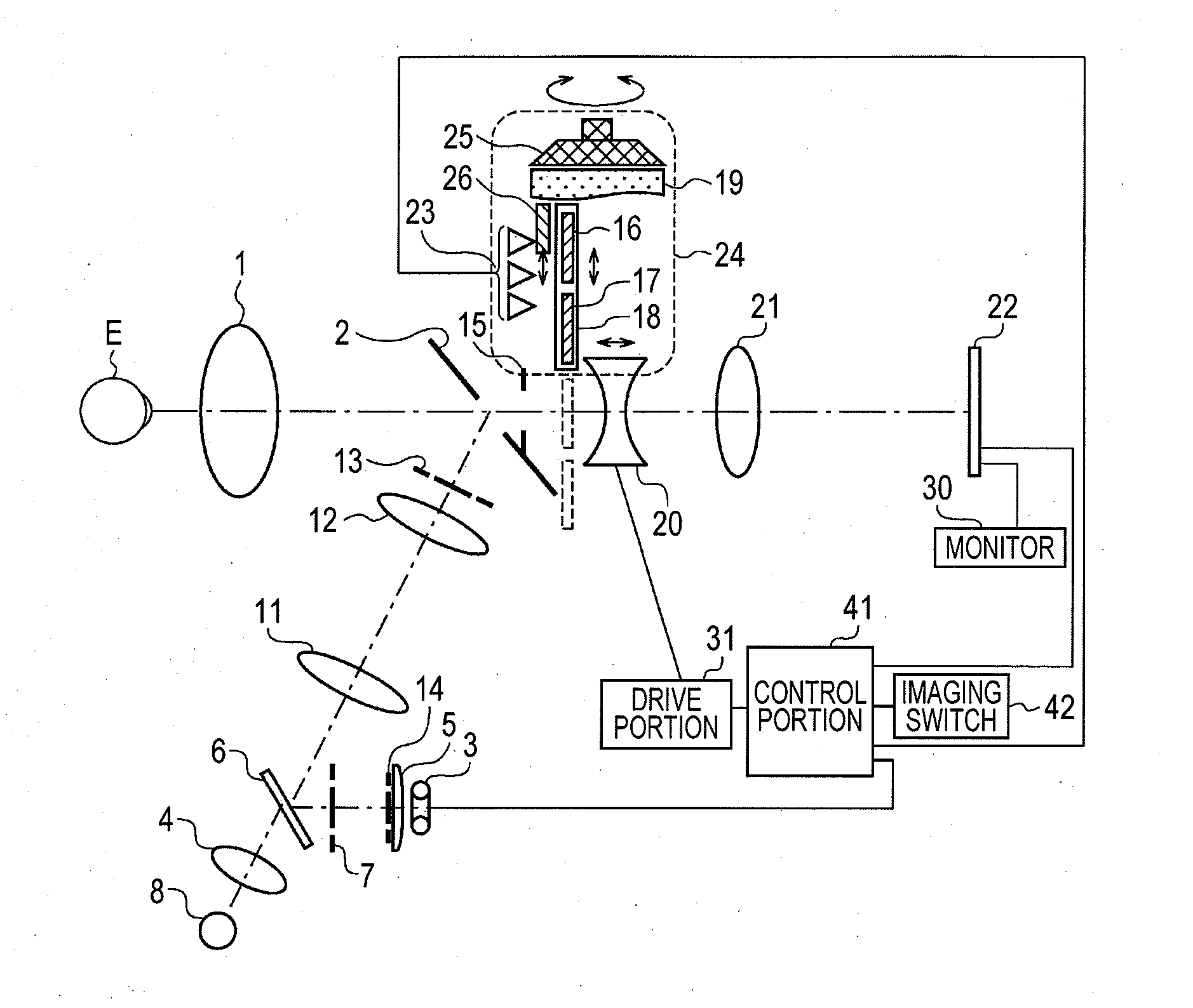
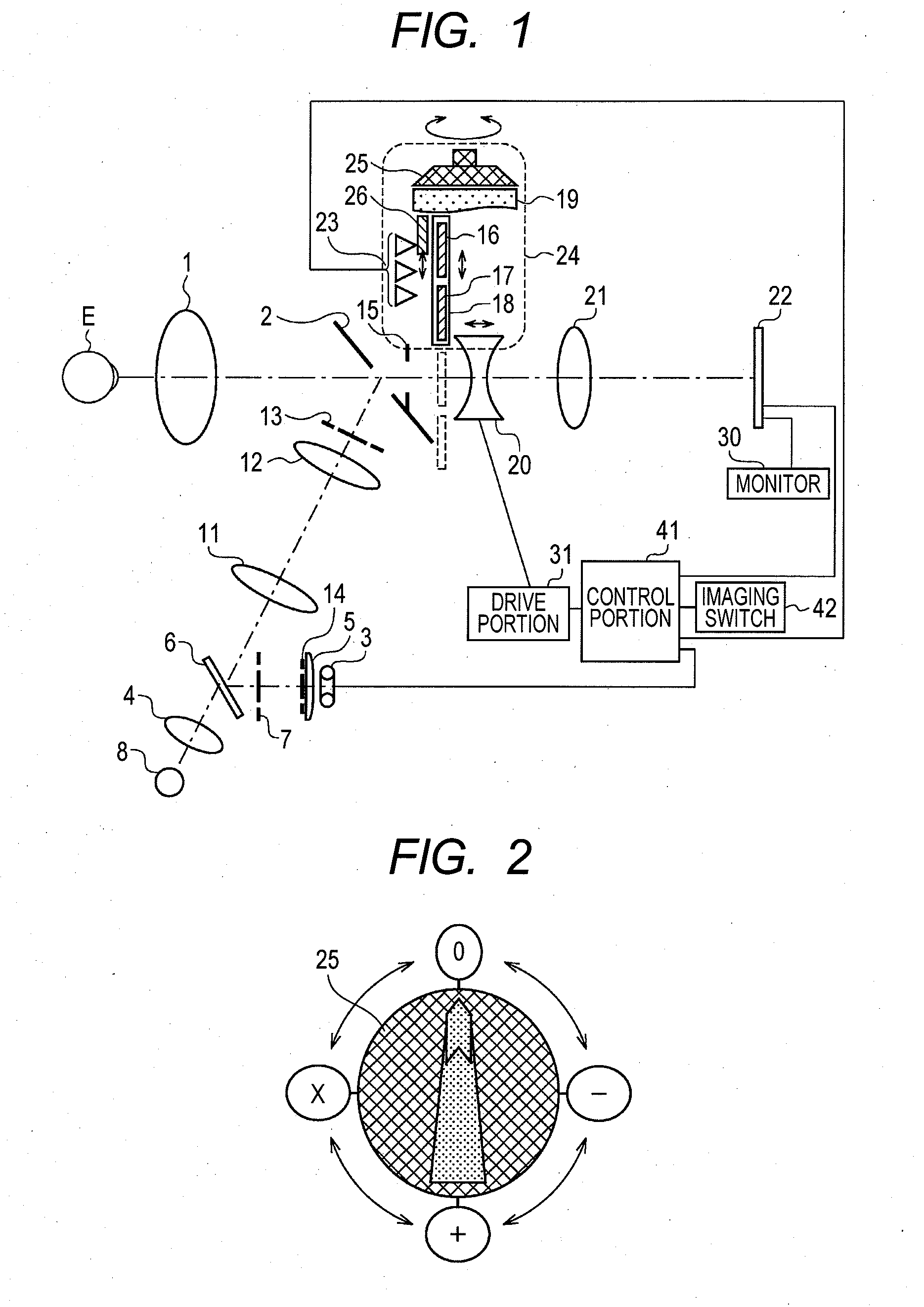
[0017]FIG. 1 is a diagram illustrating a configuration of the non-mydriatic fundus camera.

[0018]The fundus camera includes a lens 4, a relay lens 11, a relay lens 12, and a cornea stop 13 having a ring-like opening portion, which are arranged in order on an optical path ranging from a near-infrared LED 8 serving as an observation illumination light source to an objective lens 1 through a perforated mirror 2. The lens 4 has a function of enhancing effectiveness of utilizing light emitted from the near-infrared LED 8. Further, the cornea stop 13 separates an illumination light beam from an imaging light beam so as to prevent adverse light (reflected light) from a cornea of an eye E to be inspected due to the illumination light beam from entering an imaging stop 15.

[0019]Further, the fundus camera includes a lens 5, a pupil stop 14 having a ring-like opening portion, and a crystalline lens stop 7 having a ring-like opening portion, which are arranged in order on an optical path ranging...

second embodiment

[0063]FIG. 4 is a view illustrating an overall configuration of the non-mydriatic fundus camera. A configuration of an optical main body 100 is the same as the configuration of FIG. 1, and description thereof is therefore omitted herein. In FIG. 4, the front side of the fundus camera is represented by “Fr”, and the rear side thereof is represented by “Rr”.

[0064]The fundus camera includes a fixed base 102 having a face receiving portion 101 fixed to the front side thereof, the face receiving portion 101 supporting the face of the subject, and a movable stage 103 movable on the fixed base 102 from front to back and from side to side, and having the optical main body 100 mounted thereto. Further, the fundus camera includes an alignment operation portion 104 for operating the movable stage 103.

[0065]When the examiner operates the alignment operation portion 104, the movable stage 103 and the optical main body 100 move from front to back and from side to side in association with each oth...


PUM


Abstract

Provided is a fundus imaging apparatus which achieves reduction of a load on an examiner by facilitating understanding of an operation of switching from a fundus imaging mode to an anterior ocular segment imaging mode, comprising: an imaging unit for taking an image of an eye to be inspected; a focusing unit for achieving a substantially conjugate relationship between the eye to be inspected and the imaging unit; a diopter adjustment unit for adjusting a diopter when the eye to be inspected is myopic or hyperopic; an imaging selecting unit capable of selecting the fundus imaging mode or the anterior ocular segment imaging mode; a diopter adjustment switching unit for switching the diopter adjustment unit in accordance with the selected imaging mode; and a drive unit for driving the focusing unit in accordance with the selected imaging mode.

Description

BACKGROUND OF THE INVENTION[0001]1. Field of the Invention[0002]The present invention relates to a fundus imaging apparatus, and more particularly, to a fundus imaging apparatus capable of imaging an anterior ocular segment of an eye to be inspected.[0003]2. Description of the Related Art[0004]Conventionally, there has been known a fundus camera capable of observing and imaging a fundus and an anterior ocular segment of an eye to be inspected. A fundus camera disclosed in Japanese Patent Application Laid-Open No. H04-317628 supports imaging of the anterior ocular segment as well by spacing the eye to be inspected away from the fundus camera, and moving a focus lens for focusing between an image of the eye to be inspected and an imaging plane in a hyperopic direction when imaging the anterior ocular segment.[0005]In a case where an examiner such as an ophthalmologist uses the fundus camera as described above for imaging the anterior ocular segment, the examiner first switches a diopt...

Claims


Application Information

Patent Timeline
Patent Type & Authority Applications(United States)
IPC IPC(8): A61B3/12
CPCA61B3/0075A61B3/156A61B3/12
Inventor OHBAN, HIDEYUKI
Owner CANON KK
Why Eureka
Try Eureka