
Projector

a projector and projector technology, applied in the field of projectors, can solve problems such as the inability to prevent the body

Active Publication Date: 2012-03-01
SEIKO EPSON CORP
View PDF18 Cites 42 Cited by
  • Summary
  • Abstract
  • Description
  • Claims
  • Application Information

AI Technical Summary

Benefits of technology

The invention is a projector that prevents damage to the fluorescent body and improves the control process by detecting and controlling the degradation of the fluorescent body. The projector includes a solid-state light source, a fluorescent body, an optical modulation device, a detection device, and a control device. The detection device detects the excitation light and fluorescence converted by the fluorescent body, and the control device controls the solid-state light source and optical modulation device based on the detection results. This prevents the light emitted from the solid-state light source from being directly output to the screen and improves the reliability and accuracy of the control process. The detection device can be positioned at a different optical path from the fluorescent body and reflect the light output from the fluorescent body, or can detect the leakage light from the solid-state light source. The control device can also perform control based on the monitoring of the power supply status of the solid-state light source. The use of a rotary fluorescent plate or specific excitation light can also improve the degradation of the fluorescent body and light emission efficiency. Overall, the invention provides a more reliable and accurate projector for color display and other applications.

Problems solved by technology

Accordingly, in the technologies disclosed in JP-A-2005-85871 and JP-A-2002-45329, a problem (a problem that the light having a high-level output emitted from the solid-state light source is directly output to the outside of the projector) that may occur due to damage in the above-described fluorescent body cannot be prevented.
In addition, in a case where the fluorescent body is degraded, the balance of three types of light (the red light, the blue light, and the green light) that are necessary for color display may collapse, so that the color of an image displayed on the screen changes from the original color.

Method used


Image

  • Projector
  • Projector
  • Projector

Examples


first embodiment

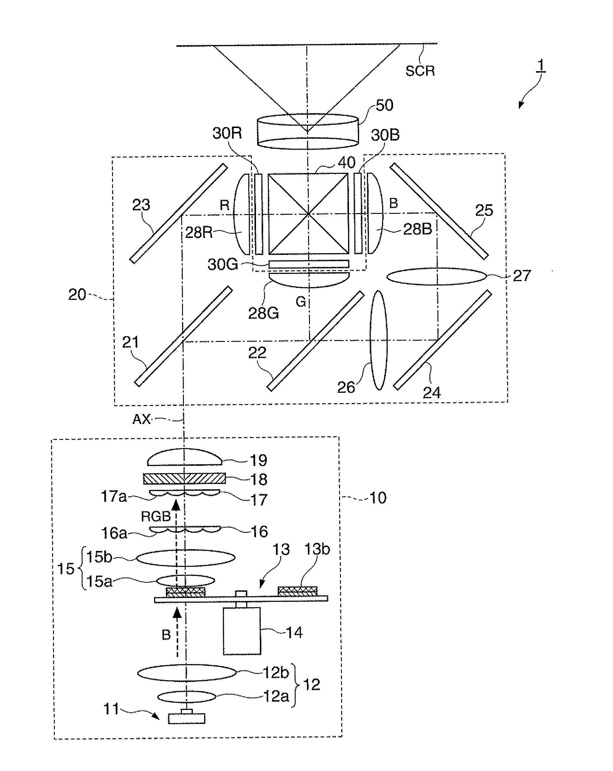
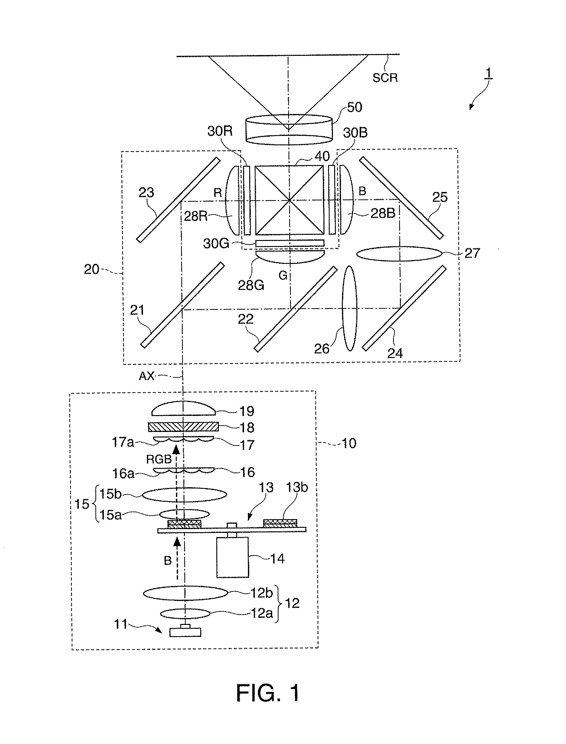
[0039]FIG. 1 is a plan view showing the entire configuration of a projector according to a first embodiment of the invention. As shown in FIG. 1, the projector 1 includes an illumination device 10, a color separating light guiding optical system 20, liquid crystal optical modulation devices 30R, 30G, and 30B (optical modulation devices), a cross dichroic prism 40, and a projection optical system 50. The projector 1 displays an image on a screen SCR by projecting image light according to an image signal input from the outside toward the screen SCR.

[0040]The illumination device 10 includes a solid-state light source 11, a light collecting optical system 12, a rotary fluorescent plate 13, a motor 14, a collimator optical system 15, a first lens array 16, a second lens array 17, a polarization converting device 18, and a superposing lens 19 and emits white light that includes red light, green light, and blue light. The solid-state light source 11 emits blue light (peak of emission inten...

second embodiment

[0082]Next, a projector according to a second embodiment of the invention will be described. The entire configuration of the projector according to this embodiment is similar to that of the projector according to the first embodiment shown in FIG. 1. However, the arrangement of the optical sensor 63 in the projector according to this embodiment is different from that in the projector according to the first embodiment. FIG. 6 is a diagram showing the configuration of a main part of the projector according to the second embodiment of the invention. In FIG. 6, for easy understanding, only members, which are similar to the configuration shown in FIG. 4, are extracted from the members shown in FIG. 1 and are shown in a simplified manner.

[0083]As shown in FIG. 6, the projector 2 according to this embodiment includes a half mirror 71 (reflection optical system) and a light collecting lens 72 in addition to the configuration shown in FIG. 4. The half mirror 71 is disposed on an optical path...

third embodiment

[0089]Next, a projector according to a third embodiment of the invention will be described. The entire configuration of the projector according to this embodiment is similar to that of the projector according to the first embodiment shown in FIG. 1. However, the arrangement of the optical sensor 63 in the projector according to this embodiment is different from those in the projectors according to the first and second embodiments. FIG. 7 is a diagram showing the configuration of a main part of the projector according to the third embodiment of the invention. In FIG. 7, similarly to FIG. 6, only members, which are similar to the configuration shown in FIG. 4, are extracted from the members shown in FIG. 1 and are shown in a simplified manner.

[0090]As shown in FIG. 7, the projector 3 according to this embodiment is configured so as to detect reflected light of blue light incident to the fluorescent body 13b by disposing the optical sensor 63 shown in FIG. 4 at a position deviated from...


PUM


Abstract

A projector includes: a light source that emits excitation light; a fluorescent body that converts the excitation light into fluorescence; a liquid crystal optical modulation device that modulates light output from the fluorescent body; an optical sensor that detects at least one of the excitation light passing through the fluorescent body and the fluorescence converted by the fluorescent body; and a control device that controls at least one of the light source and the liquid crystal optical modulation device based on a detection result of the optical sensor.

Description

BACKGROUND[0001]1. Technical Field[0002]The present invention relates to a projector.[0003]2. Related Art[0004]As is widely known, a projector is a device that includes a light source, an optical modulation device, and a projection lens and displays an image on a screen by modulating light emitted from the light source by using the optical modulation device and projecting the modulated light onto the screen by using the projection lens. Generally, projectors include a lamp such as a halogen lamp, a metal halide lamp, or a high-pressure mercury lamp as the light source. However, recently, in order to achieve low power consumption, miniaturization, lightness, and the like, projectors including solid-state light sources such as an LD (Laser Diode) and an LED (Light Emitting Diode) have been actively developed.[0005]As one type of projector including a solid-state light source, there is a projector in which red light, blue light, and green light necessary for color display are acquired ...

Claims


Application Information

Patent Timeline
Patent Type & Authority Applications(United States)
IPC IPC(8): G03B21/20F21V9/40
CPCG02B2207/113G03B21/204H04N9/3155H04N9/3194H04N9/3182H04N9/3158
Inventor TSUDA, MASAHIDESAITO, OSAMUSHIOIRI, KENICHIYANASE, SHIGEHIRO
Owner SEIKO EPSON CORP
Learn More