Battery pack

a battery pack and battery technology, applied in the field of batteries, can solve the problems of large amount of solder used and complicated assembly process, and achieve the effect of reducing the height of the solder portion and improving the reliability of the coupling

Active Publication Date: 2012-03-01
SAMSUNG SDI CO LTD
View PDF4 Cites 24 Cited by
  • Summary
  • Abstract
  • Description
  • Claims
  • Application Information

AI Technical Summary

Benefits of technology

[0016]As described above, in the connection circuit board of embodiments of the present invention and the battery pack including the same, when a multi-cell is connected to a printed circuit module in series or parallel, a height of a solder portion can be minimized.
[0017]In addition, in the connection circuit board of the present invention and the battery pack including the same, coupling reliability can be improved by maximizing a contact area of a conductive lead and a solder portion of the connection circuit board.

Problems solved by technology

However, in order to increase a coupling force between the PCM and the unit cell, a large amount of solder may be used.
Accordingly, space for mounting other elements in the PCM is minimal, that is, distances between each of the elements are narrow, which may make the assembly process complicated.

Method used


Image

  • Battery pack
  • Battery pack
  • Battery pack

Examples


Embodiment Construction

[0033]Hereinafter, a connection circuit board and a battery pack including the same according to embodiments of the present invention with reference to the accompanying drawings will be described in more detail.

[0034]A connection circuit board according to an aspect of the present invention and a battery pack including the same will first be described.

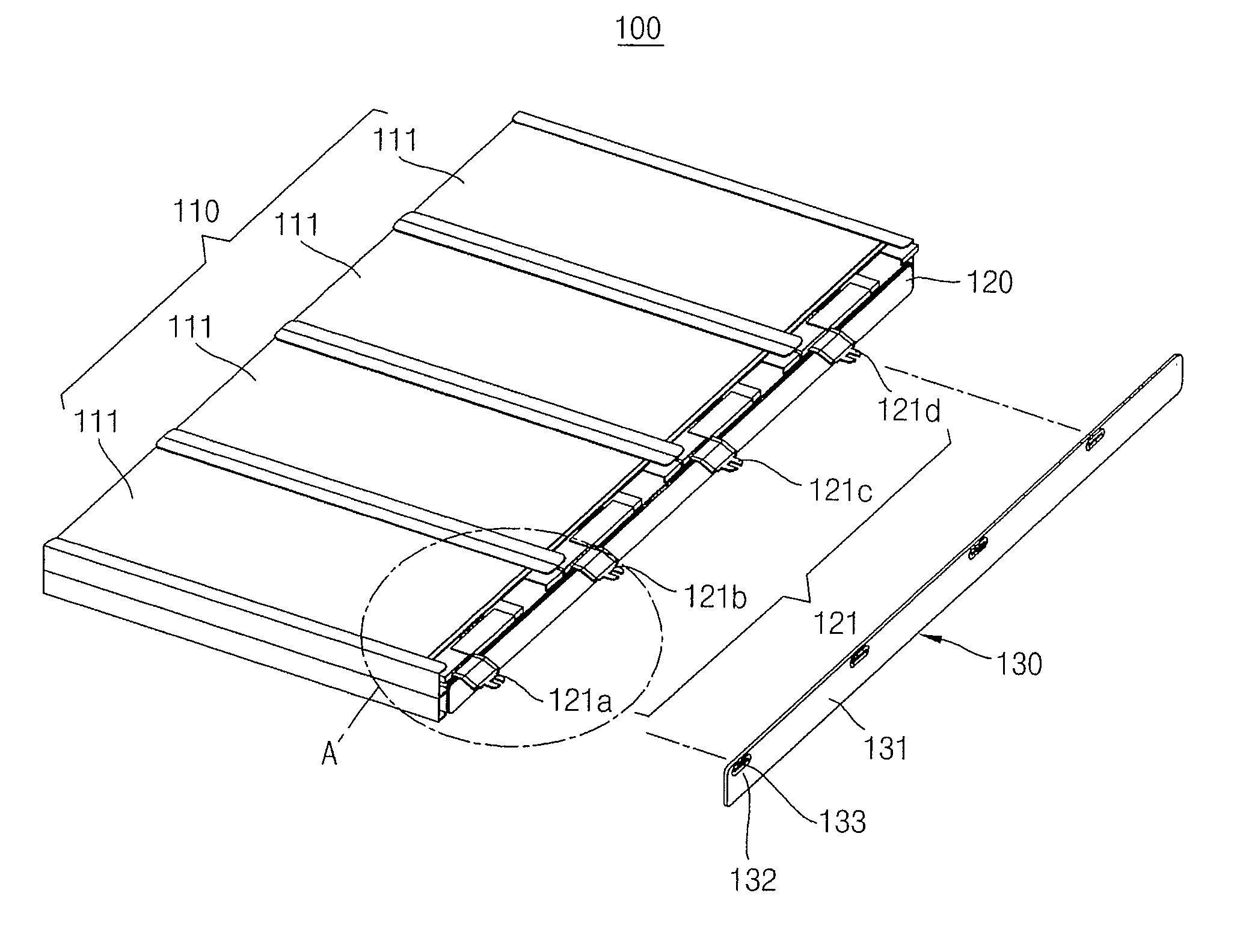
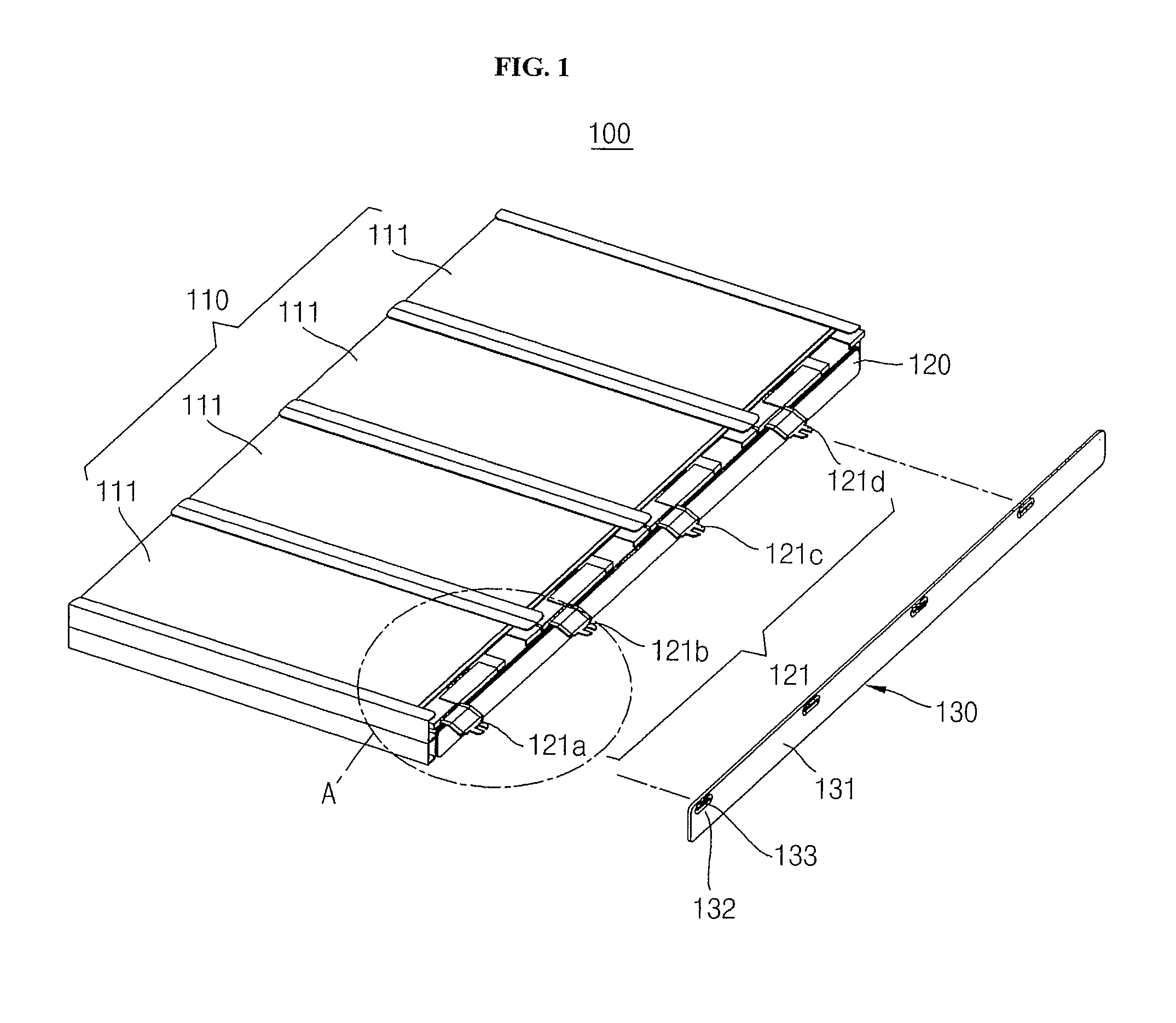
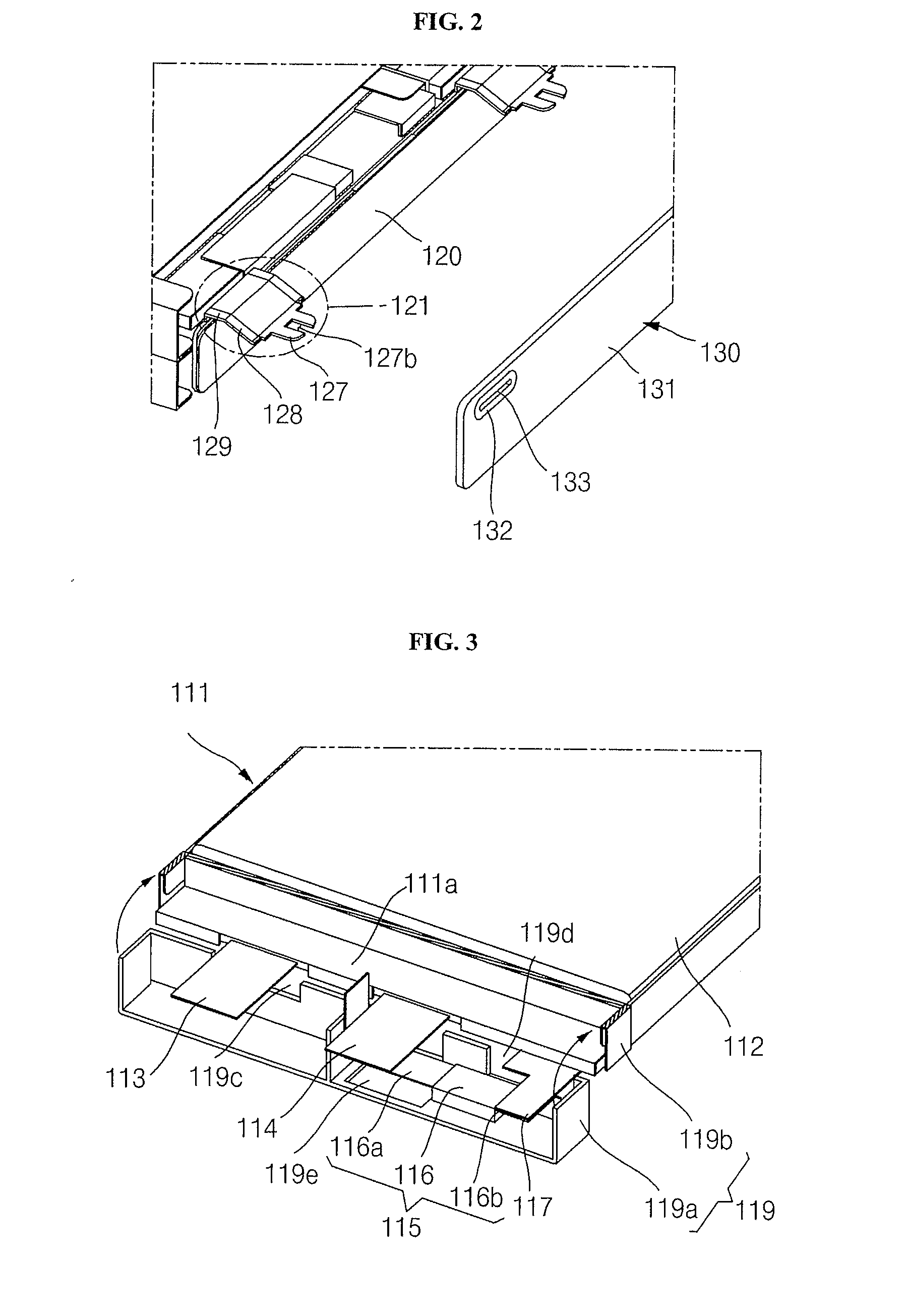
[0035]FIG. 1 is a perspective view of a battery pack according to an embodiment of the present invention, FIG. 2 is an enlarged perspective view of a portion A of FIG. 1, FIG. 3 is a partially perspective view of a unit cell constituting the battery pack shown in FIG. 1, FIG. 4 is a partially perspective view illustrating a connection relationship between the unit cell shown in FIG. 3 and a connection circuit board, FIG. 5 is a perspective view illustrating a conductive lead and an opening shown in FIG. 1 are separated from each other, FIG. 6 is a front view of a soldering connection of FIG. 5, and FIG. 7 is a vertical section view tak...


PUM

PropertyMeasurementUnit
widthaaaaaaaaaa
height W1aaaaaaaaaa
height W1aaaaaaaaaa

Abstract

Provided is a battery pack having improved product reliability by reducing a height of a solder portion connected when at least two or more unit cells are connected to a printed circuit module in series or parallel.
Aspects of the present invention provide a battery pack including a connection circuit board. The battery pack includes a multi-cell, a connection circuit board connected to the unit cells, a conductive lead drawn out from the connection circuit board, a printed circuit module having an opening into which the conductive lead is inserted, a solder portion formed by solder connection in which the conductive lead is inserted into the opening, wherein the conductive lead has an insertion portion inserted into the opening, a bent portion bent from the insertion portion, and a recess by which the insertion portion is divided.

Description

CROSS-REFERENCE TO RELATED APPLICATIONS[0001]This application claims the benefit of U.S. Provisional Application No. 61 / 377,392, filed on Aug. 26, 2010, in the United States Patent and Trademark Office, the disclosure of which is incorporated herein in its entirety by reference.BACKGROUND[0002]1. Field[0003]Aspects of the present invention relate to a battery pack.[0004]2. Description of Related Art[0005]A battery pack typically includes a multi-cell assembly having a plurality of unit cells, and a printed circuit module (PCM).[0006]The unit cells include a bare cell exclusively performing charging / discharging operations only.[0007]The PCM includes a field effect transistor (FET) as a switching element that blocks current, a resistor, condenser, etc. The PCM controls charging / discharging operations of the unit cell, and prevents over-charge, over-discharge, over-current, etc.[0008]The PCM is often electrically connected to the unit cell by soldering.[0009]However, in order to increa...

Claims


Application Information

Patent Timeline
Patent Type & Authority Applications(United States)
IPC IPC(8): H01M2/00H01M50/502H01M50/519H01M50/528H01M50/533H01M50/536
CPCH01M2/202H05K3/3426H01M10/425H05K2201/09427H05K2201/10037H05K3/363Y02E60/10H01M50/502H01M50/533H01M50/536H01M50/519H01M50/572H01M50/543H01M50/528H01M10/42
Inventor PARK, SANGHUN
Owner SAMSUNG SDI CO LTD
Why Eureka
Try Eureka