Apparatus and System for a Resistance Training System

a resistance training and apparatus technology, applied in the field of fitness equipment, can solve the problems of reducing the resolution of weight selection, easy to get injured when using the system, and heavy weight stack devices, so as to mitigate user injury, reduce vibration, and reduce the effect of weigh

Inactive Publication Date: 2012-03-01
ZHU ZHENGMAO
View PDF3 Cites 65 Cited by
  • Summary
  • Abstract
  • Description
  • Claims
  • Application Information

AI Technical Summary

Benefits of technology

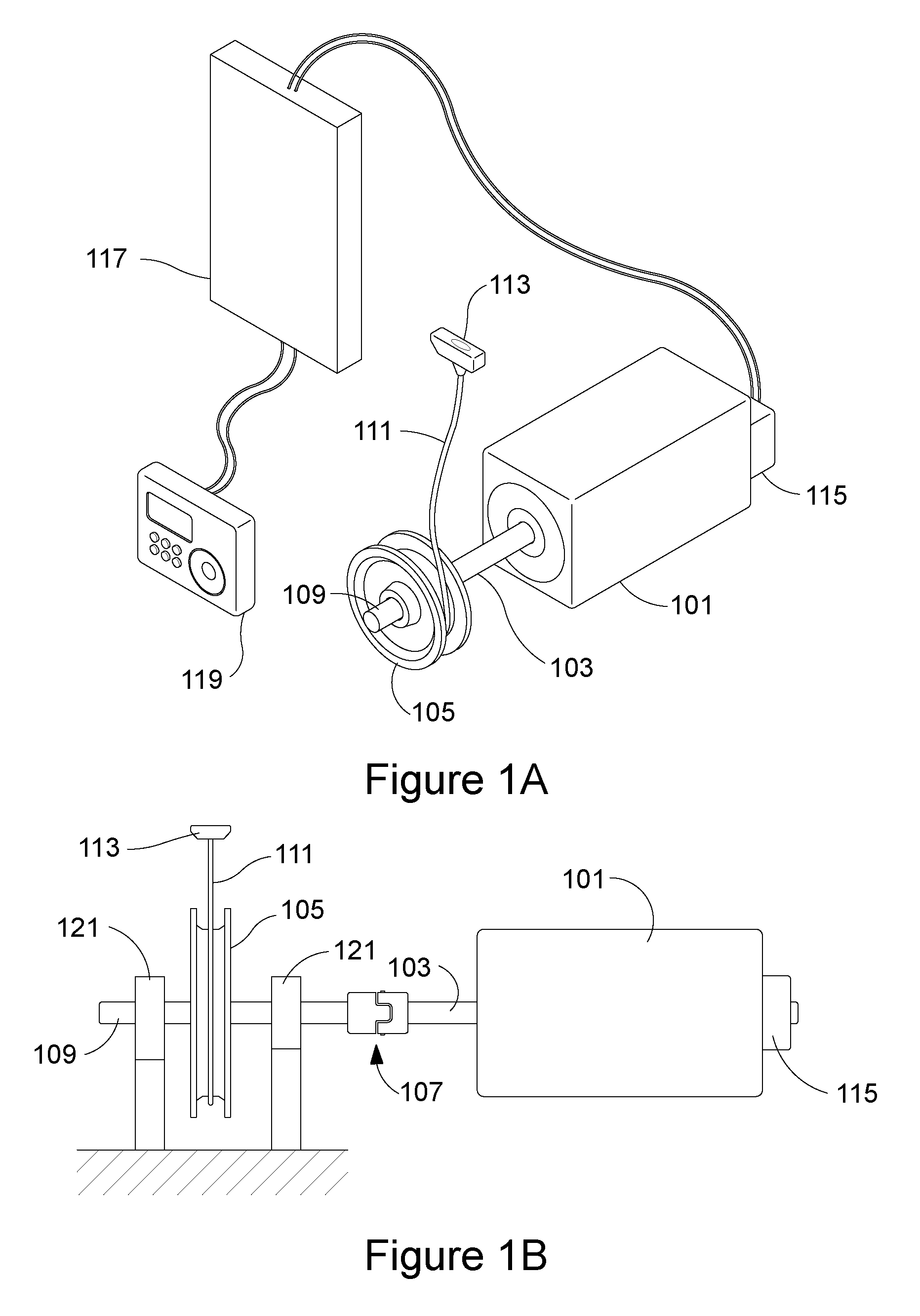
[0021]In another embodiment a system includes an output shaft, means for exerting torque on the output shaft, means for sensing and for outputting a rotational position of the output shaft, means for transferring a force element to a user engaging in resistance training using the system, and means, in communication with the exerting means and the sensing means, for controlling exerting means to exert a predetermined torque during user operation of the system for resistance training. Another embodiment further includes means for converting a rotational motion to a linear motion, and means for joining the transferring means to the output shaft. Yet another embodiment further includes means for enabling user setting of at least a value corresponding to the predetermined torque. Still another embodiment further includes means for mitigating vibration. Another embodiment further includes means for enabling the joining means to be pulled in a plurality of directions.
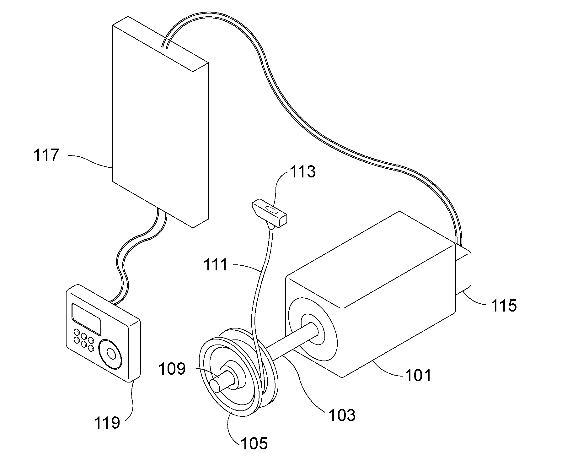
[0022]In another embodiment a system includes an output shaft. An electrically controlled motor exerts torque on the output shaft. An encoder senses and outputs a rotational position of the output shaft. A handle is joined to the output shaft for transferring a force element to a user engaging in resistance training using the system. A controller is in communication with the electrically controlled motor and the encoder for controlling the electrically controlled motor to exert a predetermined torque during user operation of the system for resistance training. Another embodiment further includes a pulley joined to the output shaft for converting a rotational motion to a linear motion, and a cable joined to the pulley, the pulley and the cable being configured for joining the handle to the output shaft. Yet another embodiment further a user interface for enabling user setting of at least a value corresponding to the predetermined torque. Still another embodiment further includes a flex coupling joining the pulley to the output shaft for mitigating vibration. Another embodiment further includes a first pair of parallel rollers having a first space between the rollers, and a second pair of parallel rollers having a second space between the rollers. The second pair of parallel rollers is positioned perpendicular to the first pair of parallel rollers where an intersection of the first space and the second space produces a third space through which the cable passes for enabling the cable to be pulled in a plurality of directions relative to the pulley. In yet another embodiment the controller communicates an electrical current profile to the electrically controlled motor for the predetermined torque. In still another embodiment the electrical current profile represents a type of the force element. In another embodiment types of the force element comprise linear and non-linear forces. In yet another embodiment the user interface displays to the user an amount of calories burned by the user. In still another embodiment absent a user applied force to the handle, the controller stops the electrically controlled motor. In another embodiment a rotational speed of the electrically controlled motor above a predetermined level initiates a modification of the electrical current profile to mitigate user injury.

Problems solved by technology

Weight stack devices are typically heavy and massive because the devices consist of actual weighted elements to provide resistance.
There are known methods to reduce the actual amount of weight in the weight stacks by using pulley systems; however, pulley systems decrease the resolution of the weight selection.
Furthermore, it is easy to get injured when using these systems.
For example, if a user is trying to push up weight that is greater than his limit, as the weight is released it may pull the user's muscle.
Spring loading types of systems are lighter than the weight stack systems; however, they tend to occupy a large amount of space to enable the spring loading rods to swing.
Also spring loading systems cannot provide linear resistance throughout the range of motion.
This greatly reduces the positive effect on the user during training.
Another problem with spring loading systems is that over a period of time the system ages and may no longer provide the indicted weight.
Thus, the user may receive false training information, which leads to bad exercise.

Method used


Image

  • Apparatus and System for a Resistance Training System
  • Apparatus and System for a Resistance Training System
  • Apparatus and System for a Resistance Training System

Examples


Embodiment Construction

[0024]The present invention is best understood by reference to the detailed figures and description set forth herein.

[0025]Embodiments of the invention are discussed below with reference to the Figures. However, those skilled in the art will readily appreciate that the detailed description given herein with respect to these figures is for explanatory purposes as the invention extends beyond these limited embodiments. For example, it should be appreciated that those skilled in the art will, in light of the teachings of the present invention, recognize a multiplicity of alternate and suitable approaches, depending upon the needs of the particular application, to implement the functionality of any given detail described herein, beyond the particular implementation choices in the following embodiments described and shown. That is, there are numerous modifications and variations of the invention that are too numerous to be listed but that all fit within the scope of the invention. Also, ...


PUM


Abstract

An apparatus and a system include an electrically controlled motor comprising an output shaft, at least one winding and a rotor for exerting torque on the output shaft. An encoder senses and outputs a rotational position of the output shaft. A pulley is joined to the output shaft for converting a rotational motion to a linear motion. A cable is joined to the pulley where at least a portion of the cable is wound about the pulley. The cable is configured for joining to a resistance training system to provide a force element. A controller is in communication with the electrically controlled motor and the encoder for controlling the electrically controlled motor to exert a predetermined torque during motion of the cable in conjunction with operation of the resistance training system.

Description

FEDERALLY SPONSORED RESEARCH OR DEVELOPMENT[0001]Not applicable.REFERENCE TO SEQUENCE LISTING, A TABLE, OR A COMPUTER LISTING APPENDIX[0002]Not applicable.COPYRIGHT NOTICE[0003]A portion of the disclosure of this patent document contains material that is subject to copyright protection. The copyright owner has no objection to the facsimile reproduction by anyone of the patent document or patent disclosure as it appears in the Patent and Trademark Office, patent file or records, but otherwise reserves all copyright rights whatsoever.FIELD OF THE INVENTION[0004]The present invention relates generally to fitness equipment. More particularly, the invention relates to an intelligent weight training resistance system.BACKGROUND OF THE INVENTION[0005]The present invention relates to weight training systems. Most current fitness weight training devices rely on weight stacks or spring loading systems to provide resistance to a user. Weight stack devices are typically heavy and massive becaus...

Claims


Application Information

Patent Timeline
Patent Type & Authority Applications(United States)
IPC IPC(8): A63B21/005
CPCA63B21/00069A63B21/00076A63B21/0058A63B21/0455A63B21/1469A63B21/152A63B21/153A63B23/1281A63B24/0087A63B2021/0059A63B2024/0065A63B2024/0081A63B2024/0093A63B2071/065A63B2220/34A63B2220/36A63B2220/44A63B2220/54A63B2225/50A63B2230/75A63B21/00196A63B21/0059A63B21/4035
Inventor ZHU, ZHENGMAO
Owner ZHU ZHENGMAO
Why Eureka
Try Eureka