Eureka AIR delivers breakthrough ideas for toughest innovation challenges, trusted by R&D personnel around the world.

Self-propelled unit for endoscope

Inactive Publication Date: 2012-03-01
FUJIFILM CORP
View PDF2 Cites 1 Cited by
  • Summary
  • Abstract
  • Description
  • Claims
  • Application Information

AI Technical Summary

Benefits of technology

[0010]In view of the foregoing problems, an object of the present invention is to provide a self-propelled unit capable of causing an endoscope to enter a body cavity smoothly, and preventing a proximal portion in a section of an elongated tube from locally contacting an endless track device.
[0022]The elongated tube includes a steering device, disposed on the distal side, and having a variable direction. The movable plate is constituted by plural movable plates arranged in a circumferential direction in the second ring sleeve. When the steering device is bent in one steering direction, one of the movable plates corresponding to the steering direction moves to the open position, so as to facilitate steering of the steering device on a proximal side.
[0024]Consequently, it is possible to cause an endoscope to enter a body cavity smoothly, and keep a steering device in the endoscope steerable readily, because the movable plate operates for shifting an endless track device away from the elongated tube.

Problems solved by technology

Manipulation of the endoscope is a difficult process, because the large intestine is a tortuous organ in a human body, and some body parts are very changeable in the position in the body, such as a sigmoid colon and a transverse colon.
Learning the manipulation of the endoscope of the large intestine requires much experience and time.
If a doctor is insufficiently skilled in the manipulation, physical load to the body of a patient will be very large.
It is very difficult to enter the self-propelled unit through the anus into the large intestine.
There is a problem in that the steering of the steering device is obstructed by the combined use of the guide assembly or the self-propelled unit, and that flexibility of the elongated tube may be lower.
Accordingly, the manipulation may be more difficult.

Method used


Image

  • Self-propelled unit for endoscope
  • Self-propelled unit for endoscope
  • Self-propelled unit for endoscope

Examples


Embodiment Construction

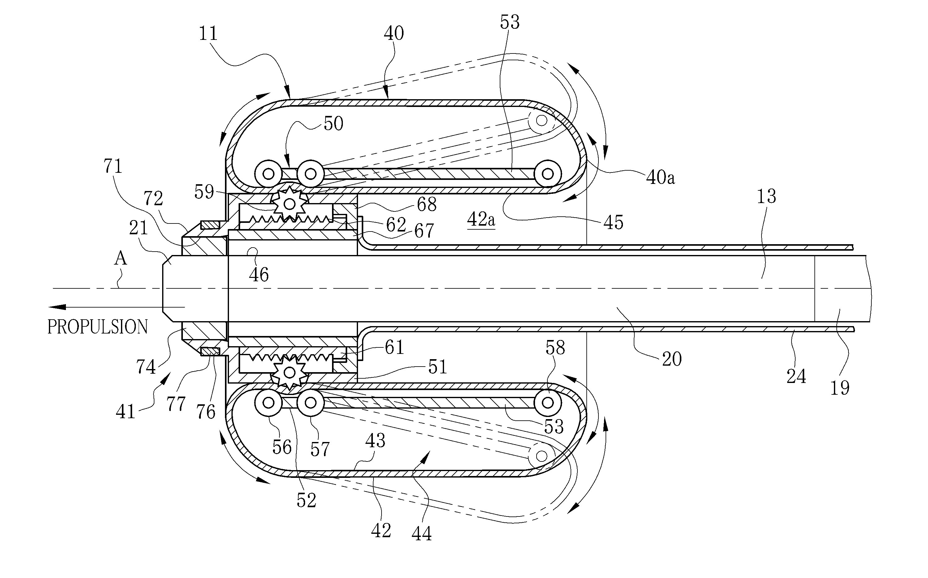
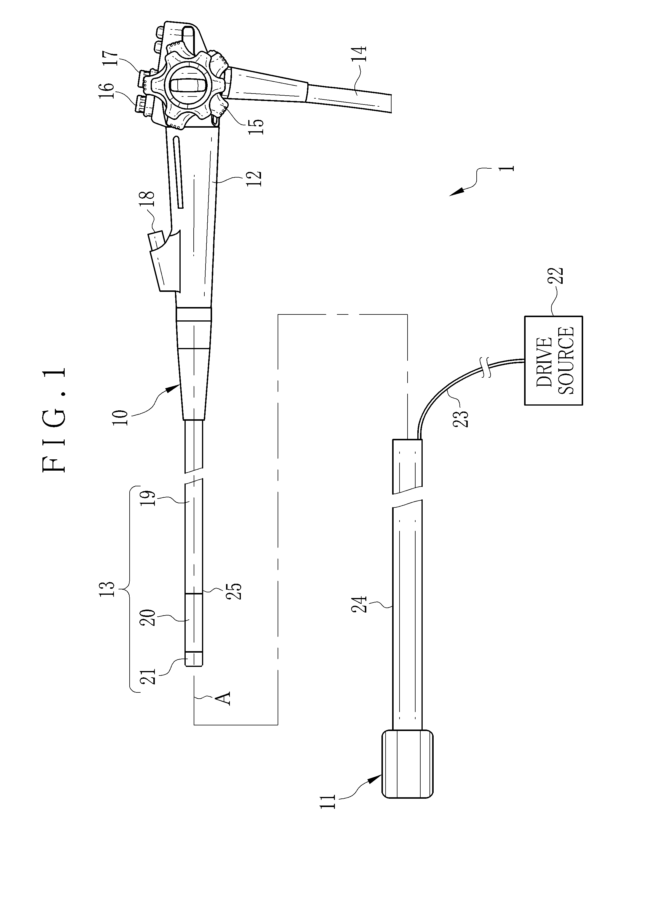
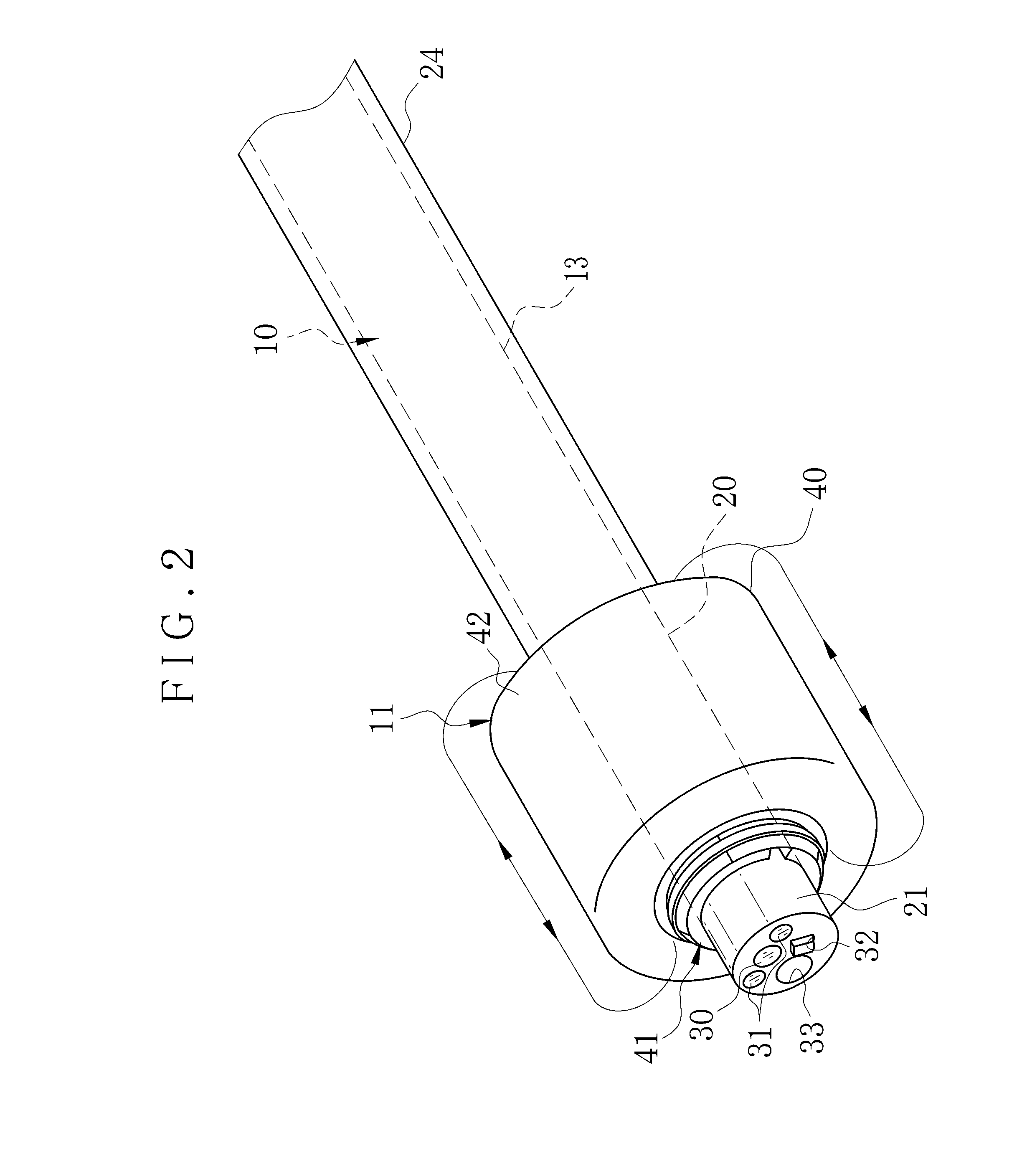
[0031]In FIG. 1, an electronic endoscope system 1 includes an electronic endoscope 10 and a self-propelled unit 11 or guide assembly. The endoscope 10 includes a handle device 12, and a section of an elongated tube 13 or guide tube extending from the handle device 12 for entry in a body cavity, for example, large intestine of a gastrointestinal tract. A universal cable 14 is connected with the handle device 12. Connectors or plugs are provided at an end of the universal cable 14 for connection with a light source apparatus (not shown) and a processing apparatus (not shown).

[0032]The handle device 12 includes steering wheels 15 for bending, an air / water button 16 and a suction button 17. The air / water button 16 is operable for supply of air or water through a distal end of the elongated tube 13. An instrument channel 18 is formed in the elongated tube 13 of the handle device 12 for receiving entry of a forceps, electrocautery device or other medical instrument.

[0033]The elongated tub...


PUM


Abstract

A self-propelled unit for an endoscope having a section of an elongated tube for entry in a body cavity is provided. A first ring sleeve is mounted around the elongated tube on a distal side in a rotatable manner. An endless track device is disposed around the first ring sleeve, having an outer annular surface, for turning around in contact with a wall of the body cavity, for propulsion in an axial direction of the elongated tube. A combination of a worm drive and an engagement roller is disposed on the first ring sleeve, for moving the endless track device.A movable plate is contained in the endless track device, movable between open and closed positions, for coming farther from the elongated tube at least locally when in the open position than when in the closed position, in order to shift the endless track device away from the elongated tube.

Description

BACKGROUND OF THE INVENTION[0001]1. Field of the Invention[0002]The present invention relates to a self-propelled unit for an endoscope. More particularly, the present invention relates to a self-propelled unit capable of causing an endoscope to enter a body cavity smoothly, and preventing a proximal portion in a section of an elongated tube from locally contacting an endless track device.[0003]2. Description Related to the Prior Art[0004]An endoscope is used to diagnose a body cavity, such as a large intestine in a gastrointestinal tract. The endoscope has a flexible elongated tube for entry in the body cavity. The elongated tube includes a head assembly, a steering device and a flexible device. The head assembly is disposed at a distal end and has a short size. The steering device is present at a proximal end of the head assembly, and keeps the head assembly steerable in a desired direction. The flexible device extends from a proximal end of the steering device and has as large a ...

Claims


Application Information

Patent Timeline
IPC IPC(8): A61B1/00
CPCA61B1/00156A61B1/0016
Inventor YAMAKAWA, SHINICHINAKAMURA, TAKAYUKIIWASAKA, MASAYUKI
Owner FUJIFILM CORP
Why Eureka
Eureka Blog
Learn More