
Apparatuses for femoral and tibial resection

a technology for femoral and tibial resection, applied in the field of methods and equipment for orthopedic surgical navigation and alignment techniques and instruments, can solve the problems of inability to consistently and/or properly locate and orient distal femoral resection in a quick and efficient manner, inconvenient operation, and inability to accurately and accurately locate distal femoral resection, etc., to minimize manual skill and reduce the need for manual skill. , the effect o

Inactive Publication Date: 2012-03-01
PUGET BIOVENTURES
View PDF5 Cites 69 Cited by
  • Summary
  • Abstract
  • Description
  • Claims
  • Application Information

AI Technical Summary

Benefits of technology

"The present invention relates to a method and apparatus for replacing knee joints with prosthetic devices. The method and apparatus can be used in total knee replacement or other applications where material needs to be removed from bones. The invention provides a cutting guide with a single slot that can be positioned to guide a saw blade across the knee joint. The guide is attached to the bone using a positioning apparatus that references the bone's geometry. The invention also includes a pattern apparatus that is oriented and fixed to the bone to prepare the bone for resection. The pattern apparatus has slot-like features that match the desired geometry of the cut. The invention also includes an ankle clamp, alignment rod, fixation head, cutting guide clamps, and a milling bit for resecting the femur. The curvilinear implant design allows for a thin implant and minimal removal of viable osseous tissue."

Problems solved by technology

Past efforts have not been successful in consistently and / or properly locating and orienting distal femoral resections in a quick and efficient manner.
Due to their use of this sub-optimal cutting tool, the instrumentation systems all possess certain limitations and liabilities.
This kind of error is further compounded by the “tolerance stacking,” inherent in the use of multiple alignment guides and cutting guides.
Another error inherent in these systems further adding to mal-alignment is deflection of the oscillating sawblade during the cutting process.
The use of an oscillating sawblade is very skill intensive as the blade will also follow the path of least resistance through the bone and deflect in a manner creating variations in the cut surfaces which further contribute to prosthesis mal-alignment as well as poor fit between the prosthesis and the resection surfaces.
Despite the fact that the oscillating saw has been used in TKA for more than 30 years, orthopedic salespeople still report incidences where poor cuts result in significant gaps in the fit between the implant and the bone.

Method used


Image

  • Apparatuses for femoral and tibial resection
  • Apparatuses for femoral and tibial resection
  • Apparatuses for femoral and tibial resection

Examples


Embodiment Construction

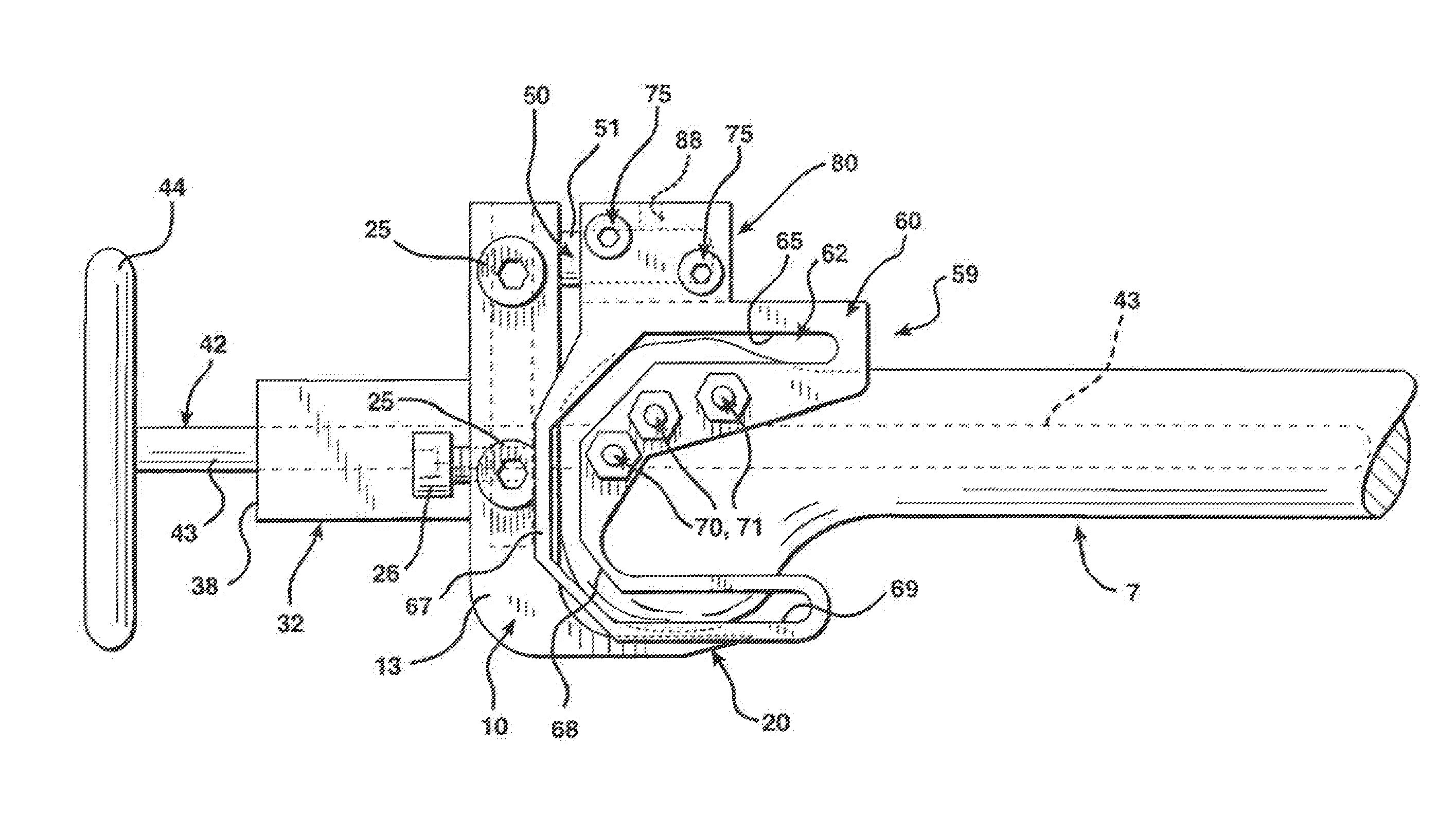
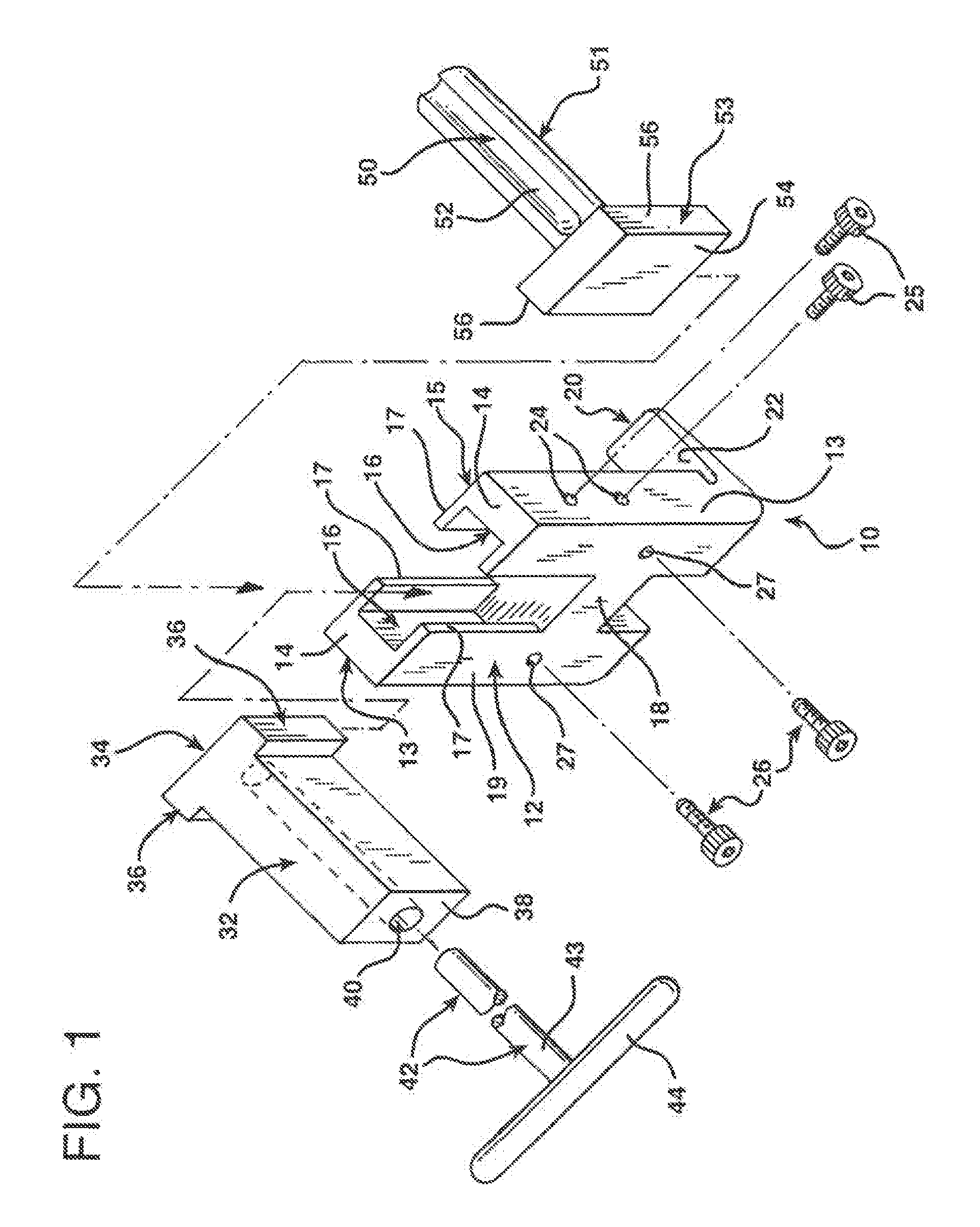
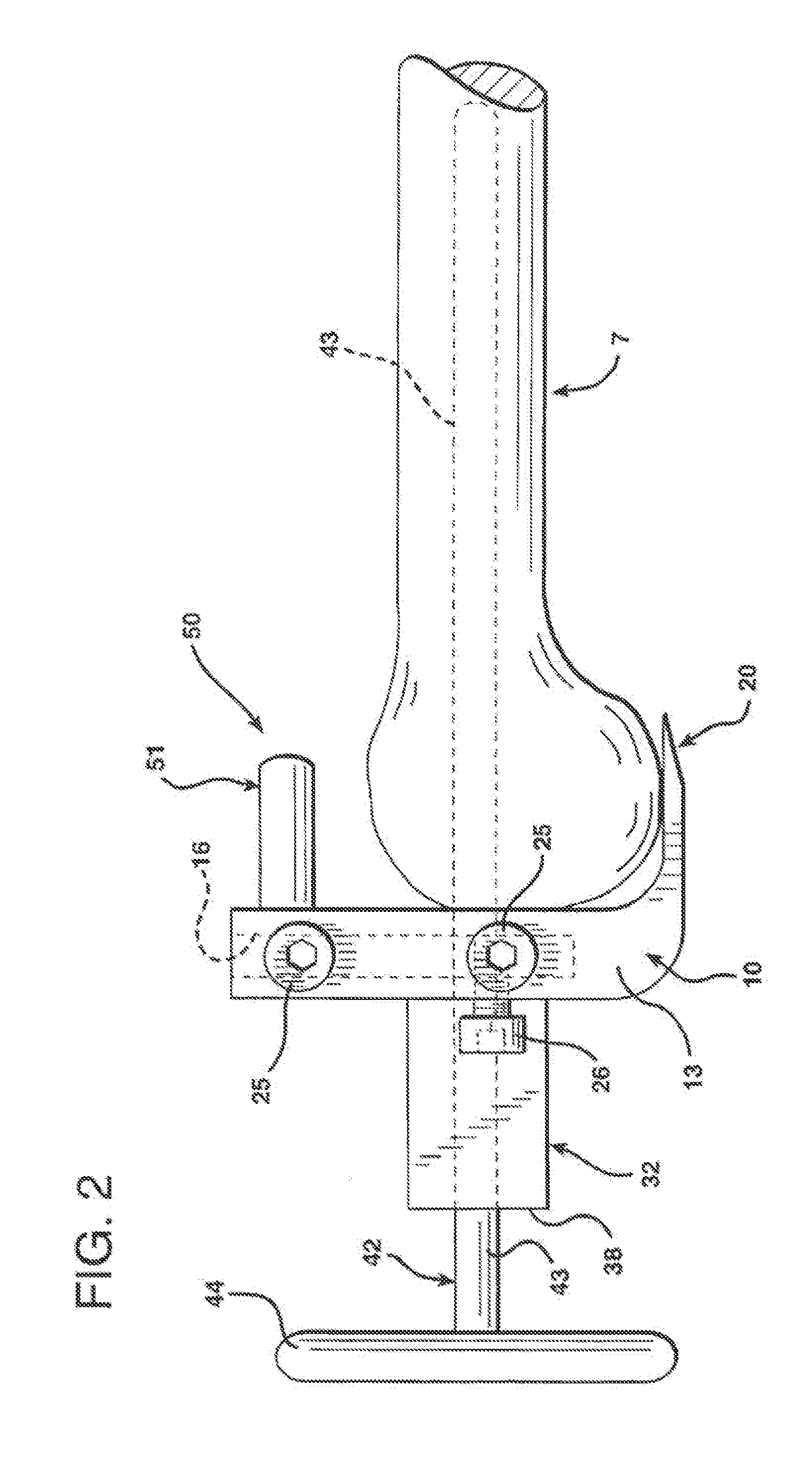
[0162]As shown generally in FIGS. 1-6, the resecting apparatus of the present invention comprises a number of components, namely positioning apparatus generally indicated at 10 comprising positioning body generally indicated at 12, angular adjustment block generally indicated at 32, rotational alignment device generally indicated at 50, pattern device generally indicated at 59 and cutting means generally indicated at 90.

[0163]As shown in detail in FIG. 1, the positioning apparatus, generally indicated at 10, includes a positioning body generally indicated at 12 having sides 13, top surface 14, front surface 15, back surface 19 and cross member 18. Extending from a lower end of the positioning body 12 is positioning tongue 20 having an upper surface 22. Extending into the positioning body 12 from top surface 14 to the cross member 18 and through the front and back surfaces 15 and 19, is a gap generally defined by slots 16 and partial slot walls 17. Sides 13 include apertures 24 for r...


PUM


Abstract

Systems for use in total knee arthroplasty include a cutting guide having only a single slot. The single slot is configured to be positioned adjacent an anterior side of the medial compartment of the knee joint with no portion positioned adjacent an anterior side of the lateral compartment of the knee joint. The single slot is adapted to guide an oscillating saw blade across the knee bone from the medial compartment to resect at least a portion of the lateral compartment. The system also includes a total knee arthroplasty implant adapted to be implanted on the resected surface.

Description

RELATED APPLICATIONS[0001]This application is a continuation of application Ser. No. 13 / 169,728 filed Jun. 27, 2011, which in turn is a continuation of application Ser. No. 10 / 977,365 filed Oct. 29, 2004, now U.S. Pat. No. 7,967,822, which in turn is a continuation of U.S. application Ser. No. 10 / 756,817 filed Jan. 13, 2004 now U.S. Pat. No. 7,344,541, which is a continuation of U.S. application Ser. No. 09 / 799,325 filed Mar. 5, 2001, now U.S. Pat. No. 6,695,848, which is a continuation-in-part of U.S. application Ser. No. 09 / 261,528, filed Mar. 3, 1999, now U.S. Pat. No. 6,197,064, which was a continuation of U.S. application Ser. No. 08 / 892,286, filed Jul. 14, 1997, now U.S. Pat. No. 5,879,354, which was a divisional of U.S. application Ser. No. 08 / 649,465, filed May 17, 1996, now U.S. Pat. No. 5,755,803, which was a continuation-in-part application of U.S. application Ser. No. 08 / 603,582, filed Feb. 20, 1996, now U.S. Pat. No. 5,810,827, which was a continuation-in-part of U.S. a...

Claims


Application Information

Patent Timeline
Patent Type & Authority Applications(United States)
IPC IPC(8): A61B17/56
CPCA61B17/14A61B17/155A61B17/157A61B17/1615A61B2017/1602A61B17/1764A61B17/72A61B17/846A61B17/1675
Inventor HAINES, TIMOTHY G.GOLDSTEIN, DAVID B.
Owner PUGET BIOVENTURES
Learn More