Flexible Annuloplasty Ring With Select Control Points

a flexible, annuloplasty technology, applied in the field of cardiac implants, can solve the problems of reducing the surgical burden of operating surgeons, scarring retraction, tear or fusion of valve leaflets, and affecting the surgical effect of surgeons, so as to achieve sufficient flexibility, maintain structural rigidity, and facilitate surgical operation. the effect of flexibility

Active Publication Date: 2012-03-01
EDWARDS LIFESCIENCES CORP
View PDF2 Cites 22 Cited by
  • Summary
  • Abstract
  • Description
  • Claims
  • Application Information

AI Technical Summary

Benefits of technology

[0017]In one embodiment a multi-stranded cable replaces solid core wire for both the tricuspid and mitral valves. Cable allows for greater deployment flexibility for minimally-invasive surgical (MIS) implant, while still maintaining the required strength and similar tensile properties of solid-core wire. In addition, selective placement of point-welds or other such control points locally control other parameters such as the ...

Problems solved by technology

Although mitral valve repair and replacement can successfully treat many patients with mitral valve insufficiency, techniques currently in use are attended by significant morbidity and mortality.
Those patients undergoing such techniques often have scarring retraction, tears or fusion of valve leaflets, as well as disorders of the subva...

Method used


Image

  • Flexible Annuloplasty Ring With Select Control Points
  • Flexible Annuloplasty Ring With Select Control Points
  • Flexible Annuloplasty Ring With Select Control Points

Examples


first embodiment

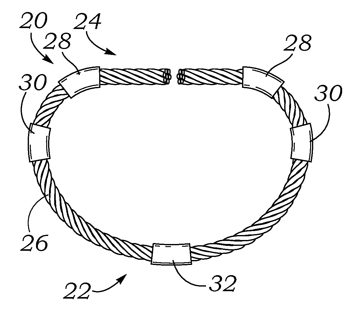
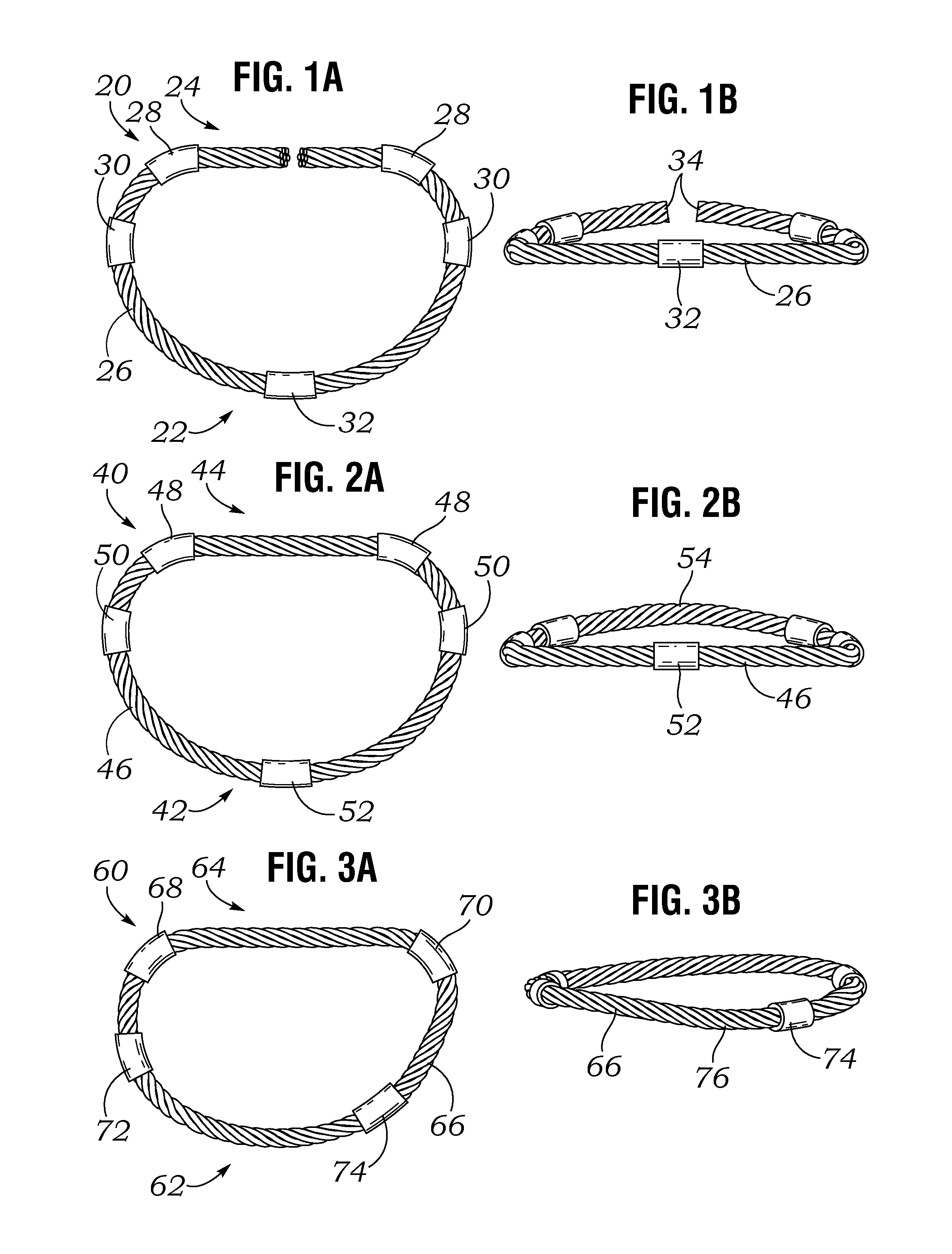
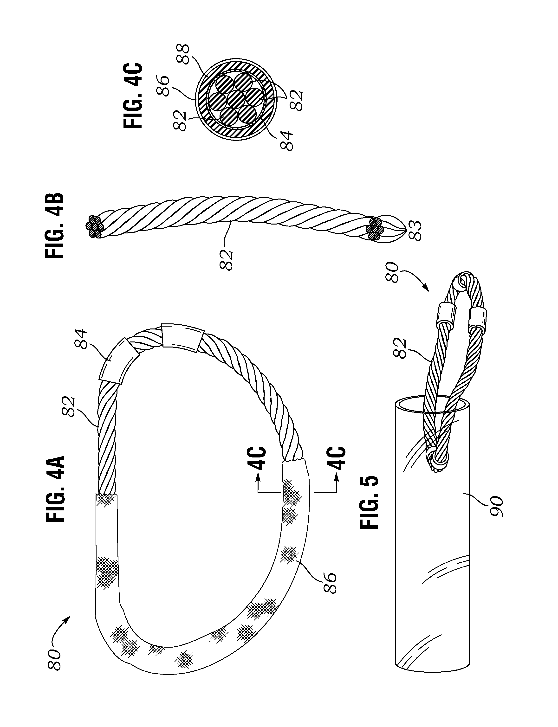
[0039]the present invention is illustrated in FIGS. 1A and 1B in which a core member 20 for a flexible mitral annuloplasty ring defines a posterior portion 22 and an anterior portion 24. Per convention, the core member 20 resembles an open D-shape with the outwardly convex posterior portion 22 and a substantially straight anterior portion 24 extending generally between commissures, or possibly the trigones, of the annulus. An annuloplasty ring that includes the core member 20 may also have a suture-permeable outer covering (not shown), such as a silicone tube surrounding the core member 20 which is then surrounded by a fabric tube. The suture-permeable covering provides anchoring material through which to pass sutures for attaching the annuloplasty ring to the annulus. The traditional construction is seen in FIGS. 4A and 4C. The present application contemplates a number of embodiments of core members 20, and it will be understood that any outer coverings known may be used.

[0040]A wo...

second embodiment

[0044]the present invention is illustrated in FIGS. 2A and 2B in which a core member 40 for a flexible mitral annuloplasty ring defines a posterior portion 42 and an anterior portion 44. As before, the core member 40 resembles a D-shape with the outwardly convex posterior portion 42 and a substantially straight anterior portion 44. However, in contrast to FIGS. 1A-1B the core member 40 has a closed peripheral shape. An annuloplasty ring that includes the core member 40 may also have a suture-permeable outer covering (not shown), such as a silicone tube surrounding the core member 40 which is then surrounded by a fabric tube, such as seen in FIGS. 4A and 4C.

[0045]The closed mitral core member 40 features the same number and location of control points or members as in the open ring above. Namely, the core member 40 is formed by a braided cable 46 having two symmetric anterior control points 48, two symmetric intermediate control points 50, and a single posterior control point 52 cente...


PUM


Abstract

An annuloplasty repair segment for heart valve annulus repair. In one embodiment a multi-stranded cable replaces solid core wire for both the tricuspid and mitral valves. Cable allows for greater deployment flexibility for minimally-invasive surgical (MIS) implant, while still maintaining the required strength and similar tensile properties of solid-core wire. In addition, selective placement of point-welds or other such control points locally control other parameters such as the amount and direction of displacement as the ring undergoes external loading. Cable with well-placed control points result in a MIS annuloplasty ring with sufficient flexibility in the x-y plane to allow a surgeon to squeeze the ring into a small incision, such as for example 1 cm×1 cm, while maintaining structural rigidity under forces exerted on the implanted ring by the cardiac cycle and allowing for asymmetrical deflection to be designed into the product.

Description

RELATED APPLICATIONS[0001]The present application claims priority under 35 U.S.C. §119 to U.S. Provisional Application Ser. No. 61 / 376,578, filed Aug. 24, 2010.FIELD OF THE INVENTION[0002]The present invention relates generally to cardiac implants and particularly to flexible annuloplasty rings especially for use in non-traditional surgeries.BACKGROUND OF THE INVENTION[0003]Prosthetic annuloplasty rings are used to repair or reconstruct damaged or diseased heart valve annuluses. In vertebrate animals, the heart is a hollow muscular organ having four pumping chambers: the left and right atria and the left and right ventricles, each provided with its own one-way valve. The natural heart valves are identified as the aortic, mitral (or bicuspid), tricuspid and pulmonary, and are each mounted in an annulus comprising dense fibrous rings attached either directly or indirectly to the atrial and ventricular muscle fibers. Each annulus defines a flow orifice.[0004]As an alternative to valve ...

Claims


Application Information

Patent Timeline
IPC IPC(8): A61F2/24
CPCA61F2/2448A61F2250/0018A61F2/2466A61F2230/0091A61F2/2445
Inventor MIGLIAZZA, JOHN F.CROCKETT, BOBABRAM, TIM
Owner EDWARDS LIFESCIENCES CORP
Why Eureka
Try Eureka