System and method for feedback control

a feedback control and system technology, applied in the field of system and method for feedback control, can solve the problems of compromising between desired behavior and technical limitations, tuning transient response performance yet not adept at enhancing other common design specifications such as noise sensitivity and stability margins, and disturbance rejection

Active Publication Date: 2012-03-01
POLYVALOR S E C
View PDF6 Cites 24 Cited by
  • Summary
  • Abstract
  • Description
  • Claims
  • Application Information

AI Technical Summary

Benefits of technology

[0010]In order to address the above and other drawbacks, there is provided a method for controlling a plant having a minimum phase transfer function P(s) and given an input signal u, the plant having an output y and a plant frequency range. The method comprises calculating a transfer function J(s) comprising the product of a fast time response high gain filter J1(s) having a gain k1 sufficient that
[0011]There is also provided a system for controlling a plant having a transfer function P(s) which is unstable and invertible and given an input signal u, the plant having an output y and a plant frequency range. The system comprises a subtractor for calculating an error signal e comprising the difference between the system input signal u and the plant output signal y, a set of sensitivity requirements smaller than a positive number ε<1 over a limited frequency range ω≦ω1 and smaller than any number M>1 over the plant frequency range, a transfer function J(s) comprising the ...

Problems solved by technology

Indeed, a gain increase to a high enough extent in certain systems can lead to oscillatory behavior and instability.
One drawback, however, is that each prior art tuning approach is optimal with respect to a selected measure of performance and a compromise between desired behavior and technical limitations must be made.
For instance, the pole placement tuning method is suitable for tuning transient response performance yet is not adept at enhancing other common design specifications such as disturbance rejection, noise sensitivity and stability margins.
Moreover, a PID compensator cann...

Method used


Image

  • System and method for feedback control
  • System and method for feedback control
  • System and method for feedback control

Examples


Embodiment Construction

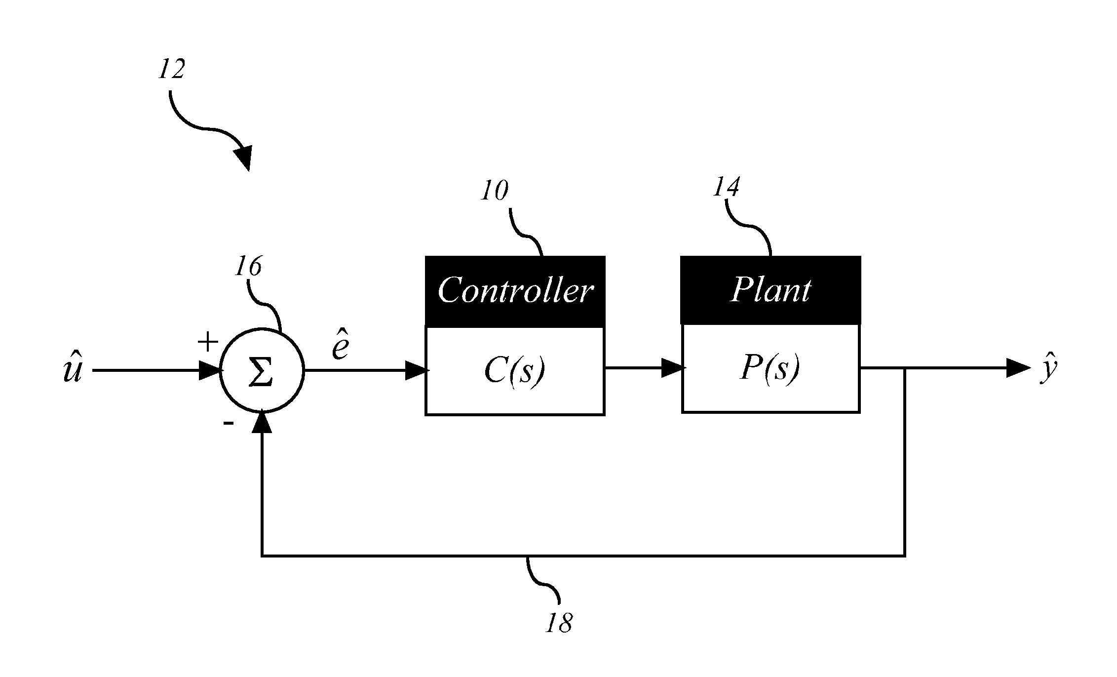
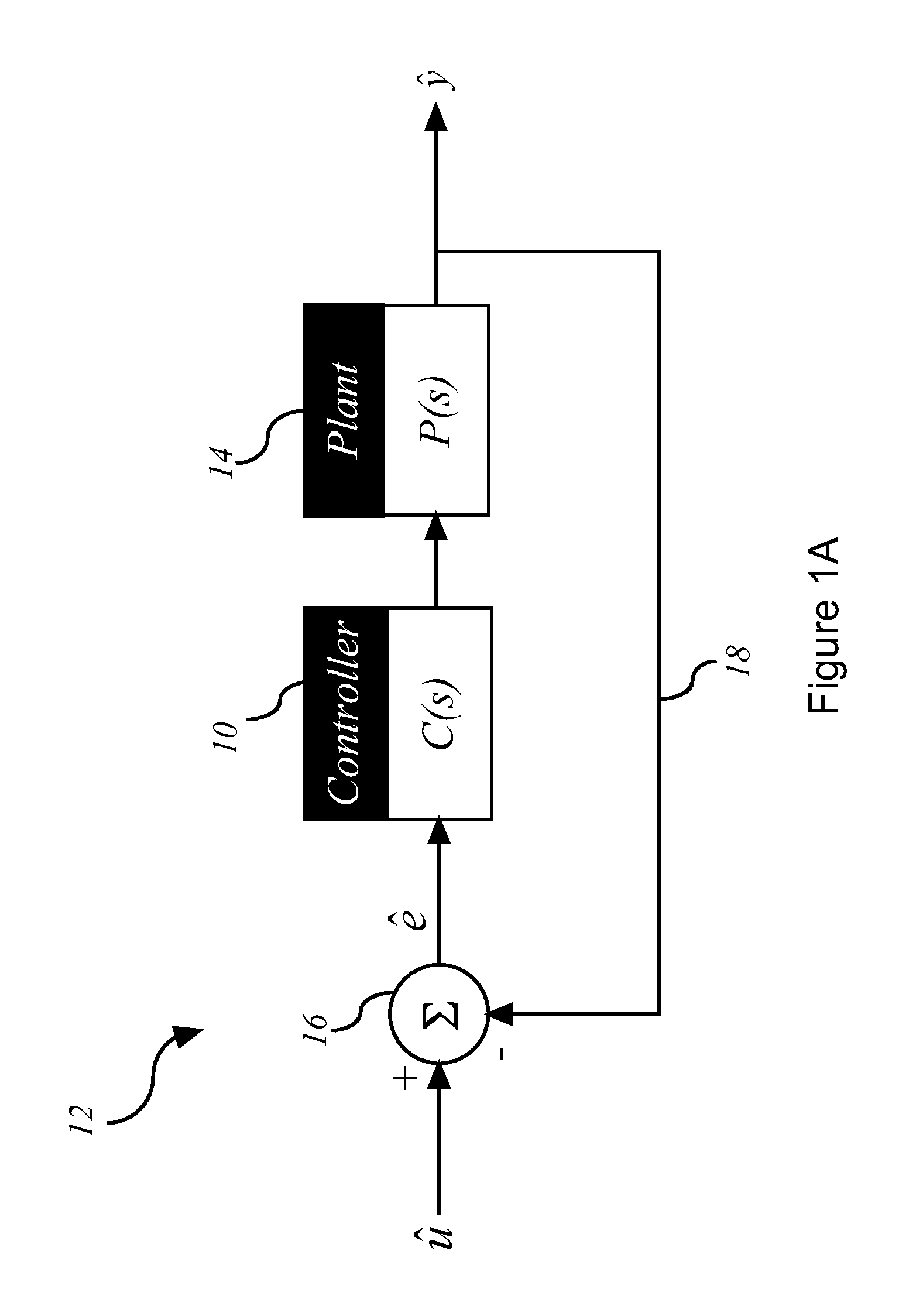
[0023]Referring now to FIG. 1A, a controller in accordance with an illustrative embodiment of the present invention and generally referred to using the reference numeral 10, will now be described in the context of a Single Input Single Output (SISO) closed-loop feedback system 12. The feedback system 12 comprises the controller 10, a plant 14, a subtractor 16, and a feedback path 18 which loops from the output of the plant 14 back to the input of the controller 10. The plant 14 is a preexisting system that does not meet all the desired frequency- and time-domain design specifications of the feedback system 12. The controller 10 is an additional system element that is added to the feedback system 12 to control the behavior of the plant 14 such that the design specifications are satisfied. In particular, the closed-loop controller 10 in accordance with an illustrative embodiment of the present invention is illustratively cascaded in series with the plant 14 to thereby control its beha...


PUM


Abstract

A system and method for controlling a plant having a minimum phase transfer function P(s) and given an input signal u, the plant having an output y and a plant frequency range comprising a transfer function J(s) comprising the product of a high gain filter J1(s) having a gain k1 sufficient that
J(ω)>[1+1ɛ]
when |ω|≦ω1 and |1+J(ω)|>1/M for all ω wherein ω1 is selected to obtain a desired time response, and a low pass filter J2(s) selected such that |1+J(ω)|>1/M for all ω and J(s) is strictly proper, wherein ε<1 and M>1 and ε and M are selected to meet a desired sensitivity requirement. An error signal e is calculated comprising the difference between the system input signal u and the plant output signal y, and the error signal modified according to the transfer function C(s)=P−1(s)J1(s)J2(s) and inputting the error signal into the plant. The system and method can be extended to unstable invertible plants. A global sensitivity bound M≧1 could also be achieved for plants including right half planes zeros. The system and method are shown applied to a read-write head positioning actuator of a hard disk drive, but can be applied equally to other systems such as electrical systems, mechanical systems, industrial processes, military applications, flight control, power generation, computer servo systems, phase lock loops and the like.

Description

CROSS REFERENCE TO RELATED APPLICATIONS[0001]This application claims benefit, under 35 U.S.C. §119(e), of U.S. provisional application Ser. No. 61 / 376,872, filed on Aug. 25, 2010, on U.S. provisional application Ser. No. 61 / 410,039, filed on Nov. 4, 2010 and on U.S. provisional application Ser. No. 61 / 423,290, filed on Dec. 15, 2010. All documents above are incorporated herein in their entirety by reference.FIELD OF THE INVENTION[0002]The present invention relates to a system and method for feedback control of a system. In particular, the present invention is concerned with a feedback controller for controlling a wide variety of linear class transfer-function based plants that is simultaneously optimizable in the time and frequency domains.BACKGROUND OF THE INVENTION[0003]Classical control theory is concerned with improving a controlled system's performance measures in both the frequency and time domains. In particular, improvement objectives of time-domain performances generally in...

Claims


Application Information

Patent Timeline
IPC IPC(8): G05B13/02
CPCG05B5/01Y02P90/02
Inventor BENSOUSSAN, DAVID
Owner POLYVALOR S E C
Why Eureka
Try Eureka