Beverage dispenser for partially frozen beverages with an improved drive and sealing system

Inactive Publication Date: 2012-03-08
GRINDMASTER CORP
6 Cites 39 Cited by

AI-Extracted Technical Summary

Problems solved by technology

Furthermore, the gear arrangements in prior art constructions are often prone to field failures as a result of heat stresses and overload.
In many cases, relatively small C-frame motors are coupled to a gear box, which, in the context of a granita machine, often results in overloading conditions and excessive heat issues.
Such overloading and excessive heat issues can reduce the life of the gears, lubricants, and bearings.
For example, excessive heat reduces the lubrica...

Method used

[0032]Furthermore, replacing prior art gear arrangements with belt and pulley arrangements minimizes the problems of heat generation and allows for the use of larger drive motors to better handle the mixing load. Also, maintenance and repair costs are reduced, as most issues with belt and pulley arrangements are more easily resolved as compared to gear arrangements.
[0033]As an additional benefit, in such a construction, cleaning of the components is much easier as compared to prior art constructions as each bowl 24a, 24b and each associated auger 50a, 50b can be readily pulled forward and removed from the dispenser as a complete assembly and taken to a wash area for cleaning.
[0034]Finally, it should be recognized that an exemplary beverage dispenser made in accordance with the present invention would include a typical cooling system 90 to produce the necessary refrigeration circuit. Specifically, evaporator coils 35 are inside the respective freezing cylinders 30a, 30b (see FIG. 7) and are in fluid communication with certain cooling components housed in a lower portion of the beverage dispenser 20. For example, as shown in the schematic view of FIG. 9, the cooling components may include a compressor 100, a condenser 102, a filter/dryer 104, an expansion valve 105a, 105b (or other refrigerant control device), a suction accumulator 108, and a suction...

Benefits of technology

[0012]In such a construction, there is no drive shaft that extends through a freezing cylinder, and therefore, there is no shaft seal in the lower front portion of the dispenser, where it would be continuously submerged in the partially frozen beverage product. Accordingly, the beverage dispenser of the present invention eliminates the attendant problems of leakage at a front shaft seal as is common in prior art constructions. Furthermore, replacing prior art gear arran...

Abstract

A beverage dispenser for partially frozen beverages includes at least one bowl for storing a beverage product, with a freezing cylinder positioned in the bowl and housing evaporator coils. The beverage dispenser further includes a cooling system for supplying a cooling medium through the evaporator coils to cool the beverage product when stored in the bowl. The beverage dispenser further includes a dispenser assembly for dispensing the beverage product from the bowl. Finally, the beverage dispenser includes an auger which rotates about the freezing cylinder, the auger including a first end positioned near a front of the beverage dispenser and a second end positioned near a rear of the beverage dispenser. The auger has a ring gear positioned at its second end, and a drive system that includes a belt and pulley arrangement rotates the auger by driving the ring gear.

Application Domain

Movable measuring chambersFrozen sweets +1

Technology Topic

Image

  • Beverage dispenser for partially frozen beverages with an improved drive and sealing system
  • Beverage dispenser for partially frozen beverages with an improved drive and sealing system
  • Beverage dispenser for partially frozen beverages with an improved drive and sealing system

Examples

  • Experimental program(1)

Example

[0022]The present invention is a beverage dispenser for partially frozen beverages with an improved drive and sealing system.
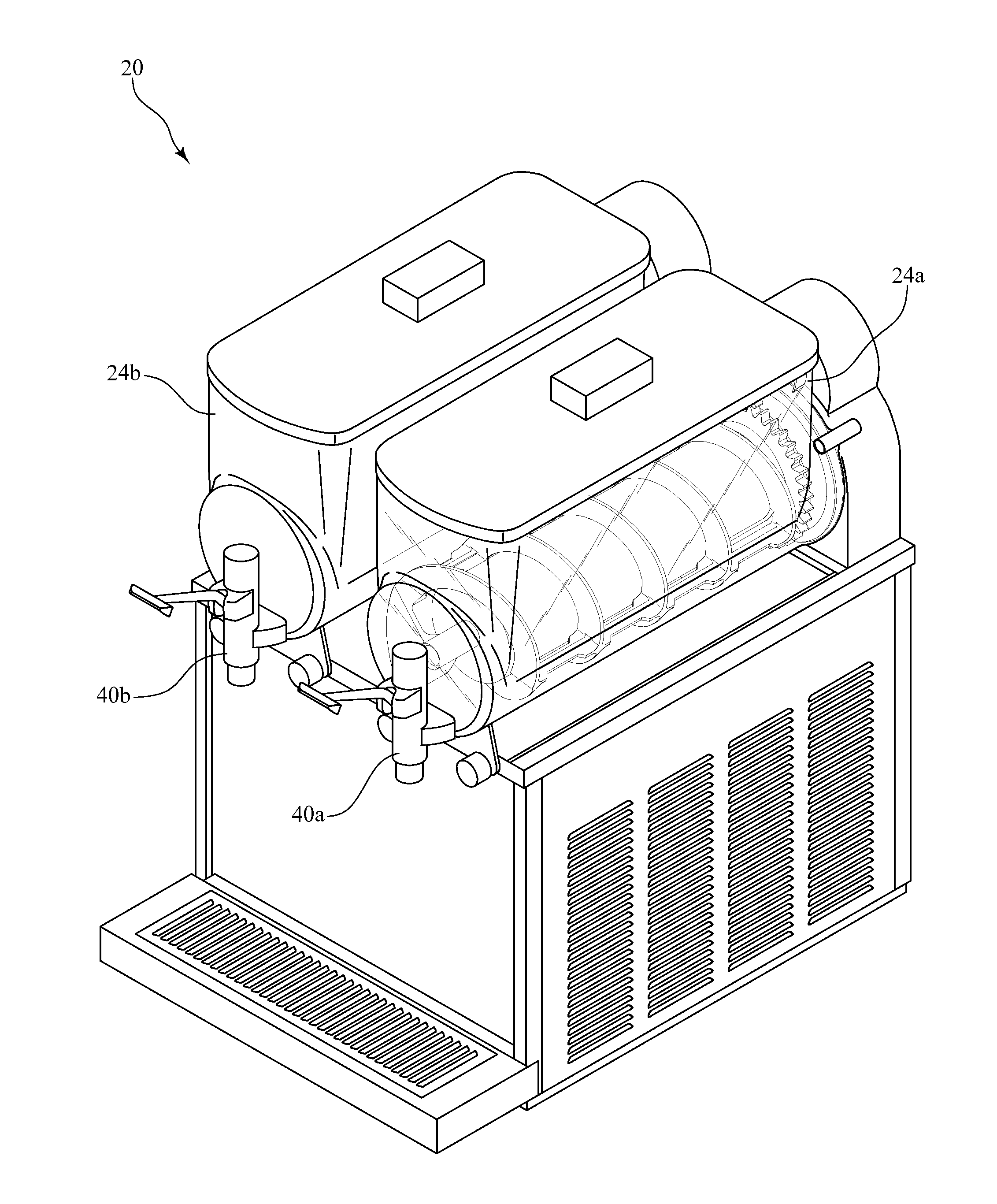
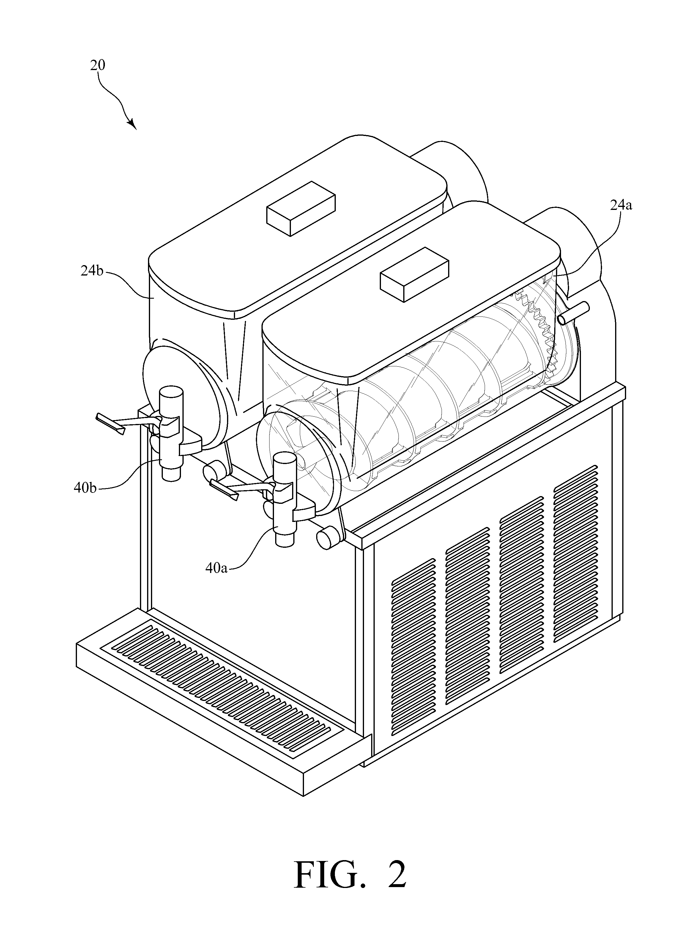
[0023]FIG. 2 is a perspective view of an exemplary beverage dispenser made in accordance with the present invention. The exemplary beverage dispenser 20 has two separate bowls 24a, 24b. However, it should be recognized that a beverage dispenser made in accordance with the present invention could have any number of bowls without departing from the spirit and scope of the present invention.
[0024]FIG. 3 is a perspective view of the same exemplary beverage dispenser 20, but with one bowl 24a hidden from view to better illustrate some of the internal components of the exemplary beverage dispenser 20.
[0025]As shown in FIGS. 2 and 3, in this exemplary beverage dispenser 20, in each bowl 24a, 24b, there is a freezing cylinder 30a, 30b, which, as mentioned above, is typical of prior art constructions. Furthermore, there is a dispenser assembly 40a, 40b at the front end of each bowl 24a, 24b for dispensing the beverage product. As is also typical in prior art constructions, in each bowl 24a, 24b, there is an auger 50a, 50b which rotates about the respective freezing cylinder 30a, 30b to shave frozen beverage product off of the surface of the freezing cylinder 30a, 30b and to circulate the beverage product within the respective bowls 24a, 24b, resulting in the partially frozen or slush-like consistency of the beverage product.
[0026]FIG. 6 is a perspective view of one of the augers 50a of the exemplary beverage dispenser 20, and FIG. 7 is a perspective view of one of the freezing cylinders 30a of the exemplary beverage dispenser 20. As shown in FIG. 6, the auger 50a is preferably a unitary member and molded from a thermoplastic material. The auger 50a includes a helical flange (or flight) 52a that is reinforced by first and second longitudinal ribs 54a, 55a that extend the length of the auger 50a. At one end, the helical flange 52a terminates in a cylindrical member 56a that defines an internal cavity 57a. As shown in FIG. 7, the freezing cylinder 30a includes a boss 32a extending from its front surface that is received in the internal cavity 57a defined by the cylindrical member 56a. Thus, once assembled, the position of the auger 50a relative to the freezing cylinder 30a is maintained, in part, by the connection of the cylindrical member 56a of the auger 50a to the boss 32a extending from the front surface of the freezing cylinder 30a; however, the auger 50a is still free to rotate relative to the freezing cylinder 30a.
[0027]Referring now to FIGS. 4 and 5, in each bowl 24a, 24b, the auger 50a, 50b is driven from the rear, and thus, there is no drive shaft that extends through the respective freezing cylinders 30a, 30b. Specifically, and referring also to FIG. 6, in this exemplary embodiment, each auger 50a, 50b is formed with an integral ring gear 58a, 58b at its second end, which, when assembled, is positioned near the rear of the beverage dispenser 20. The ring gear 58a is engaged by a drive gear 62a, and the other ring gear 58b is similarly engaged by a drive gear 62b. The first drive gear 62a is rotated by a belt and pulley arrangement, and the second drive gear 62b is rotated by a substantially identical belt and pulley arrangement.
[0028]Referring now to FIGS. 4 and 5, along with the rear view of FIG. 8, in this exemplary embodiment, in each belt and pulley arrangement, a first pulley 70a, 70b is mounted to a common shaft 72a, 72b with the respective drive gear 62a, 62b. Each first pulley 70a, 70b is then operably connected to a respective second pulley 74a, 74b by a respective first belt 80a, 80b. In this exemplary embodiment, the ratio of the diameter of each first pulley 70a, 70b to the diameter of each second pulley 74a, 74b is 4:1.7.
[0029]Referring still to FIGS. 4 and 5, along with the rear view of FIG. 8, each second pulley 74a, 74b is mounted on another shaft 75a, 75b with a third pulley 76a, 76b, such that each second pulley 74a, 74b rotates with the corresponding third pulley 76a, 76b on the shaft 75a, 75b. The third pulley 76a, 76b is then operably connected to a respective fourth pulley 78a, 78b by a respective second belt 82a, 82b. In this exemplary embodiment, the ratio of the diameter of each third pulley 76a, 76b to the diameter of each fourth pulley 78a, 78b is 5:1.7 The fourth pulley 78a is driven by a motor 90a, which, through the belt and pulley arrangement described above, causes the drive gear 62a to drive the ring gear 58 to rotate the auger 50a. Similarly, the other fourth pulley 78b is driven by a motor 90b, which, through the belt and pulley arrangement described above, causes the drive gear 62b to drive the ring gear 58b to rotate the auger 50b.
[0030]In this exemplary embodiment, as a result of the respective ratios described above, each drive gear 62a, 62b is driven and rotates at a speed of 155 RPM when the respective motors 90a, 90b are operating at a speed of 1075 RPM. Furthermore, because there is a gear ratio of 3.5:1 between the respective drive gears 62a, 62b and the ring gears 58a, 58b, the augers 50a, 50b effectively rotate at a speed of 44 RPM.
[0031]As mentioned above, in such a construction, there is no drive shaft that extends through the respective freezing cylinders 30a, 30b, and therefore, there is no shaft seal in the lower front portion of the dispenser 20, where it would be continuously submerged in the partially frozen beverage product. Accordingly, the beverage dispenser 20 of the present invention eliminates the attendant problems of leakage at a front shaft seal as is common in prior art constructions.
[0032]Furthermore, replacing prior art gear arrangements with belt and pulley arrangements minimizes the problems of heat generation and allows for the use of larger drive motors to better handle the mixing load. Also, maintenance and repair costs are reduced, as most issues with belt and pulley arrangements are more easily resolved as compared to gear arrangements.
[0033]As an additional benefit, in such a construction, cleaning of the components is much easier as compared to prior art constructions as each bowl 24a, 24b and each associated auger 50a, 50b can be readily pulled forward and removed from the dispenser as a complete assembly and taken to a wash area for cleaning.
[0034]Finally, it should be recognized that an exemplary beverage dispenser made in accordance with the present invention would include a typical cooling system 90 to produce the necessary refrigeration circuit. Specifically, evaporator coils 35 are inside the respective freezing cylinders 30a, 30b (see FIG. 7) and are in fluid communication with certain cooling components housed in a lower portion of the beverage dispenser 20. For example, as shown in the schematic view of FIG. 9, the cooling components may include a compressor 100, a condenser 102, a filter/dryer 104, an expansion valve 105a, 105b (or other refrigerant control device), a suction accumulator 108, and a suction line 110. As is common in such cooling systems, the compressor 100 compresses the cooling medium, preferably a refrigerant gas such as R404a (a commercially available hydrofluorocarbon refrigerant), to raise the temperature and stored energy of the cooling medium. Therefore, the cooling medium exits the compressor 100 and enters the condenser 102 as a hot, high pressure gas. In the condenser 102, the heat from the pressurization of the cooling medium is dissipated, and the cooling medium reverts to a liquid form, but remains at a high pressure. The cooling medium then passes through a filter drier 104, which is designed to filter out contaminants and dry the cooling medium to prevent ice formation. As it exits the filter drier 104, the cooling medium is separated into two streams, one associated with each freezing cylinder 30a, 30b. In each case, the cooling medium passes through an expansion valve 105a, 105b, each of which serves as a pressure-reducing device and meters the cooling medium into the evaporator coils 35 of the respective freezing cylinders 30a, 30b. Because of the pressure drop, the cooling medium evaporates, absorbing heat as it does so. By the time the cooling medium exits the evaporator coils 35, returning to the compressor 100 through a suction accumulator 108 and associated suction line 110, it again is a cool, low-pressure gas.
[0035]One of ordinary skill in the art will also recognize that additional embodiments are possible without departing from the teachings of the present invention. This detailed description, and particularly the specific details of the exemplary embodiment disclosed therein, is given primarily for clarity of understanding, and no unnecessary limitations are to be understood therefrom, for modifications will become obvious to those skilled in the art upon reading this disclosure and may be made without departing from the spirit or scope of the invention.

PUM

no PUM

Description & Claims & Application Information

We can also present the details of the Description, Claims and Application information to help users get a comprehensive understanding of the technical details of the patent, such as background art, summary of invention, brief description of drawings, description of embodiments, and other original content. On the other hand, users can also determine the specific scope of protection of the technology through the list of claims; as well as understand the changes in the life cycle of the technology with the presentation of the patent timeline. Login to view more.

Similar technology patents

Shoes

InactiveCN102038315AEasy to cleanSolesEngineering
Owner:WUJIANG YUANXING SHOES

Water surface cleaning machine

InactiveUS20060102532A1Quick cleanEasy to cleanFloating sedimentation devicesFiltration separationMarine engineeringSolar cell
Owner:CADOTTE ROLAND JR

Classification and recommendation of technical efficacy words

  • Minimizes problem
  • Easy to clean

Liquid crystal display device

ActiveUS20080291354A1Minimizes problemStable and firm structureNon-linear opticsLiquid-crystal displayEngineering
Owner:LG DISPLAY CO LTD

Cleaning Tool for Attachment Surfaces

InactiveUS20100000040A1Facilitate selective applicationEasy to cleanBoard cleaning devicesCarpet cleanersEngineeringMedical treatment
Owner:RETRACTABLE TECH INC
Why Eureka
Try Eureka