Variable valve timing control apparatus

a timing control and valve technology, applied in mechanical equipment, machines/engines, output power, etc., can solve the problems of strange sound, inability to perform feedback control, and worse start-up properties of engines

Active Publication Date: 2012-03-08
DENSO CORP
View PDF7 Cites 25 Cited by
  • Summary
  • Abstract
  • Description
  • Claims
  • Application Information

AI Technical Summary

Benefits of technology

[0010]In view of the foregoing and other problems, it is an object of th

Problems solved by technology

However, when a malfunction is generated in a system that controls the VCT phase, for example, when an actual VCT phase cannot be calculated by a break in a line that transmits a crank signal or a cam signal, the feedback control cannot be performed.
In this case, because the VCT phase may be unable to be locked into the middle lock phase, start-up property of the engine may get worse at the next engine activation time.
Because the proj

Method used


Image

  • Variable valve timing control apparatus
  • Variable valve timing control apparatus
  • Variable valve timing control apparatus

Examples


first embodiment

[0039](First Embodiment)

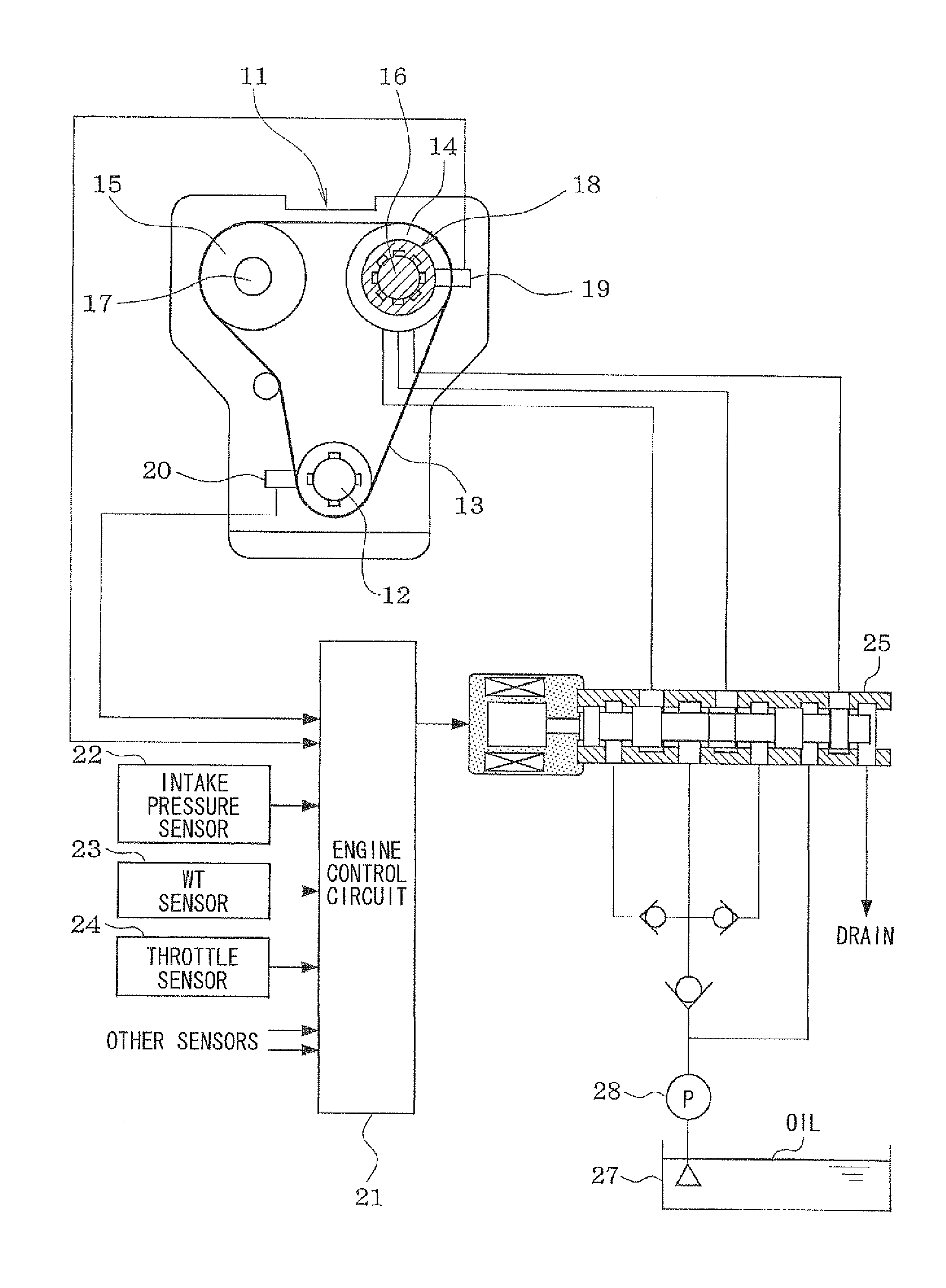
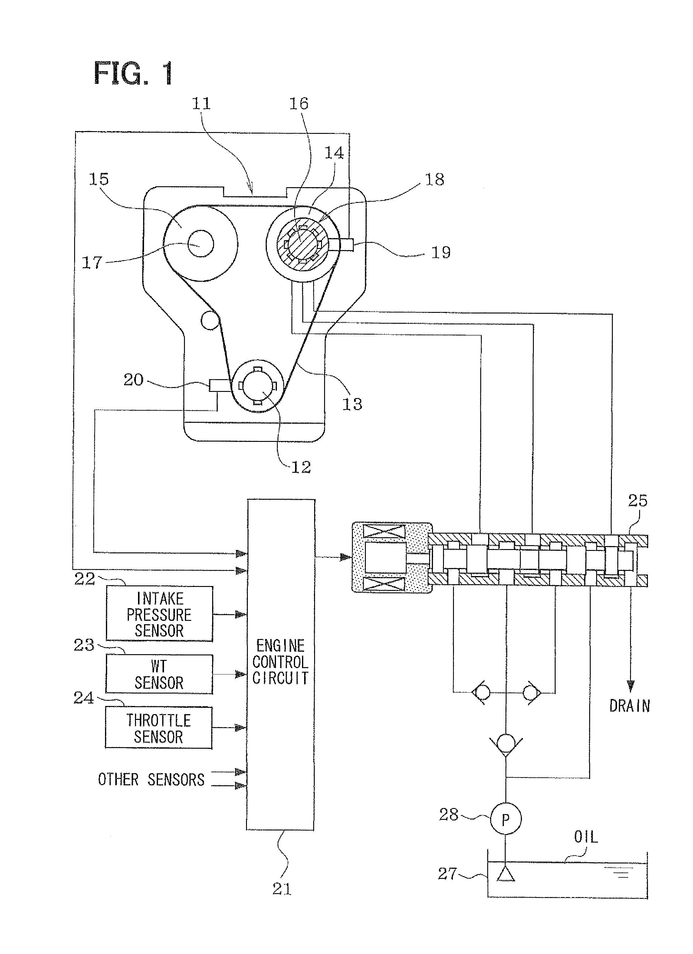
[0040]A first embodiment will be described with reference to FIGS. 1-7. As shown in FIG. 1, power is transmitted from a crankshaft 12 to an intake-side camshaft 16 and an exhaust-side camshaft 17 through respective sprocket 14, 15 by a timing chain 13, in an engine 11. The intake-side camshaft 16 has a variable valve timing device 18 to control an advance amount of the intake-side camshaft 16 with respect to the crankshaft 12, which is referred as variable cam timing (VCT) phase.

[0041]A cam sensor 19 is arranged on an outer circumference side of the intake-side camshaft 16, and outputs a pulse of cam angle signal by every predetermined cam angle. A crank sensor 20 is arranged on an outer circumference side of the crankshaft 12, and outputs a pulse of crank angle signal by every predetermined crank angle. Signals output from the sensors 19, 20 are input into an engine control circuit 21.

[0042]The engine control circuit 21 calculates an actual valve timing (act...

second embodiment

[0097](Second Embodiment)

[0098]A second embodiment will be described with reference to FIGS. 8 and 9. Substantially the same parts as the first embodiment are omitted or simplified, and parts different from the first embodiment will be described.

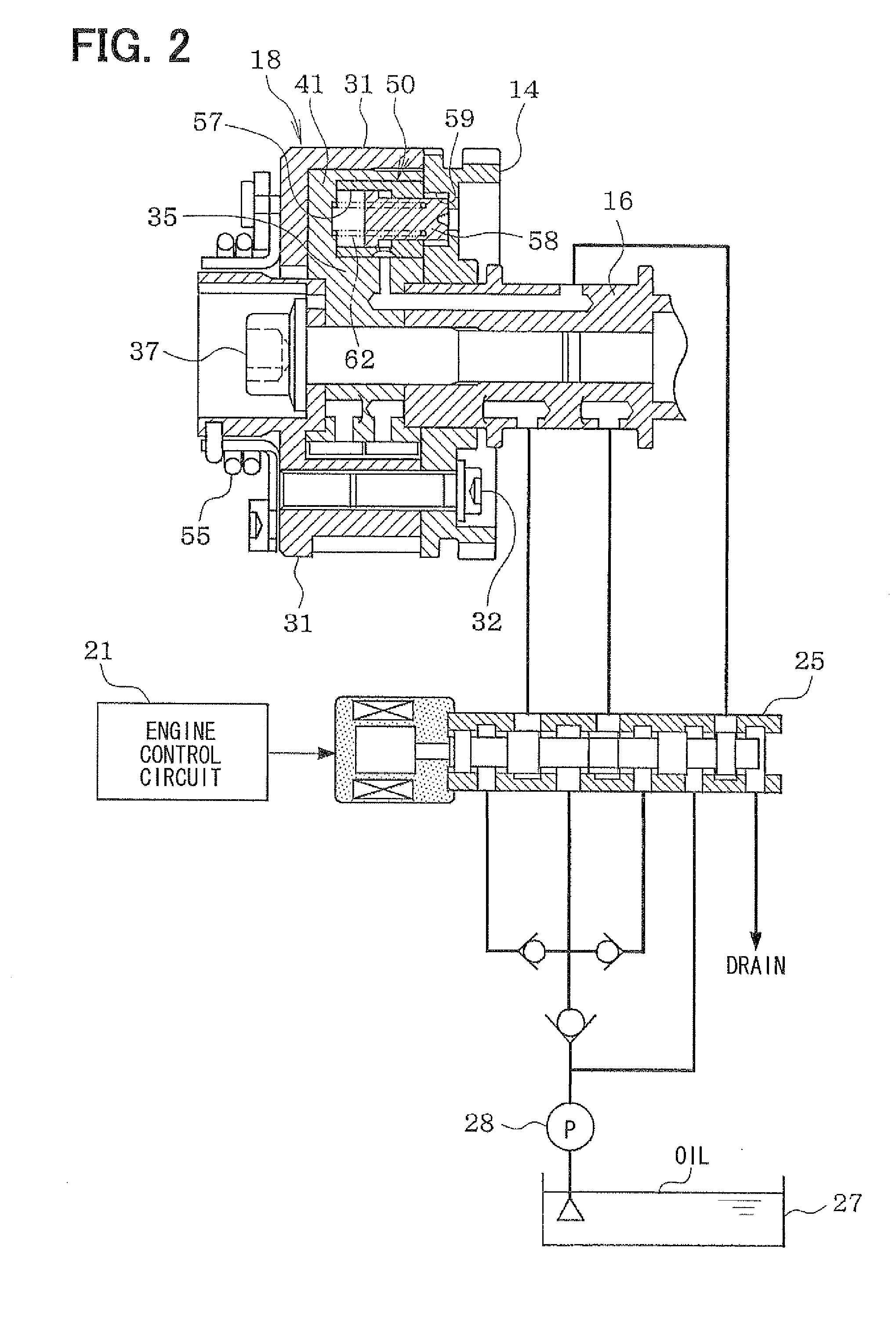
[0099]A routine of FIG. 8 and a routine of FIG. 9 are performed by the engine control circuit 21, so as to predict a generation of engine stall. Further, if the engine stall is predicted to occur, the control duty of the OCV 25 is set to have the lock holding mode L2 regardless of a position of the VCT phase. Thus, the lock pin 58 and the retard restricting pin 64 are driven to the lock direction so as to lock the VCT phase.

[0100](Lock Control for Engine Stall)

[0101]The routine of FIG. 8 is repeatedly performed with a predetermined cycle while the circuit 21 is active, and may correspond to a valve controller for engine stall. If the routine is started, a routine of predicting the engine stall (FIG. 9) to be mentioned later will be first per...


PUM


Abstract

A variable valve timing control apparatus includes an abnormality determining portion and a valve controller. The abnormality determining portion determines whether there is an abnormality in a system of a VCT phase control in which an oil pressure control valve is controlled in a manner that an actual VCT phase coincides with a target phase. The valve controller controls the oil pressure control valve to drive a lock pin in a locking direction so as to lock the VCT phase when the abnormality determining portion determines that there is an abnormality in the system of the VCT phase control.

Description

CROSS REFERENCE TO RELATED APPLICATION[0001]This application is based on Japanese Patent Application No. 2010-197074 filed on Sep. 2, 2010, the disclosure of which is incorporated herein by reference in its entirety.BACKGROUND OF THE INVENTION[0002]1. Field of the Invention[0003]The present invention relates to a variable valve timing control apparatus.[0004]2. Description of Related Art[0005]JP-A-2002-357105 (US 2002 / 0139332 A1) describes an oil-pressure drive type variable valve timing device for an engine, in which a rotation phase of a camshaft with respect to a crankshaft is locked into a predetermined lock phase when the engine is stopped. The rotation phase of the camshaft with respect to the crankshaft is defined as variable cam timing (VCT) phase. The lock phase is set into an approximately middle in a controllable range of the VCT phase, so as to enlarge a controllable range of the valve timing. The middle lock phase is set suitably for start-up of the engine. The engine i...

Claims


Application Information

Patent Timeline
IPC IPC(8): F01L1/344
CPCF01L1/3442F01L2001/3443F01L2001/34459F01L2001/34463F01L2001/34466F01L2001/34469Y02T10/18F01L2250/02F01L2800/00F01L2800/12F01L2820/041F01L2820/042F02D13/0238F01L2001/34483Y02T10/12
Inventor NAKAMURA, TAKAYOSHIURUSHIHATA, HARUYUKI
Owner DENSO CORP
Why Eureka
Try Eureka