
Solar module with light-transmissive edge seal

a solar module and edge seal technology, applied in the field of solar modules, can solve problems such as the danger of solar modules being installed

Inactive Publication Date: 2012-03-08
FIRST SOLAR INC (US)
View PDF4 Cites 21 Cited by
  • Summary
  • Abstract
  • Description
  • Claims
  • Application Information

AI Technical Summary

Problems solved by technology

As a result, solar modules may be dangerous when being installed and handled since exposing the module to light causes the module to generate electricity.

Method used


Image

  • Solar module with light-transmissive edge seal
  • Solar module with light-transmissive edge seal
  • Solar module with light-transmissive edge seal

Examples


Embodiment Construction

[0016]In the following detailed description, reference is made to the accompanying drawings which form a part hereof, and in which is shown by way of illustration specific embodiments that may be practiced. These embodiments are described in sufficient detail to enable those skilled in the art to make and use them, and it is to be understood that structural, logical, or procedural changes may be made to the specific embodiments disclosed without departing from the spirit and scope of the invention.

[0017]Electrical output from a solar module typically depends on the surface area of the active material available for active light collection. Increasing the surface area of the active material without increasing the module footprint increases the energy output rating of the module. That said, to reduce the risk of electrical shock, a minimum distance, called the “tracking distance,” between the active material and an exposed outer surface of the module needs to be maintained. U.S. Patent...


PUM


Abstract

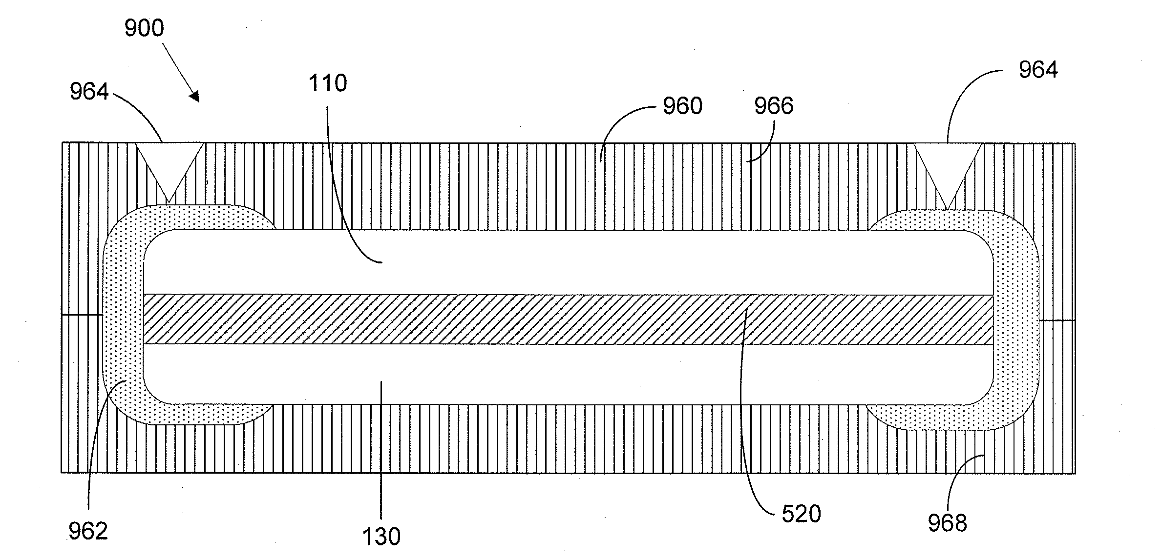
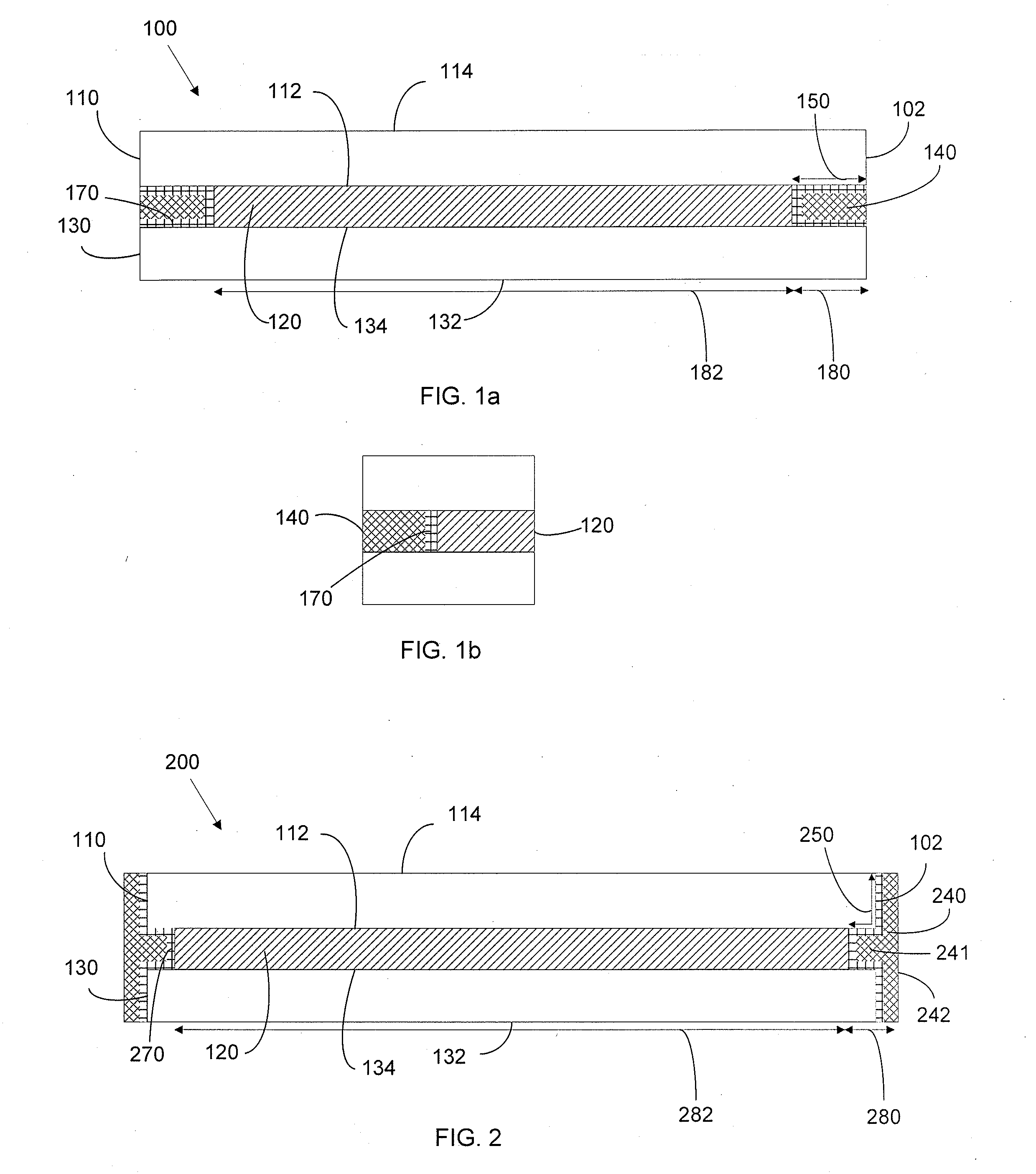
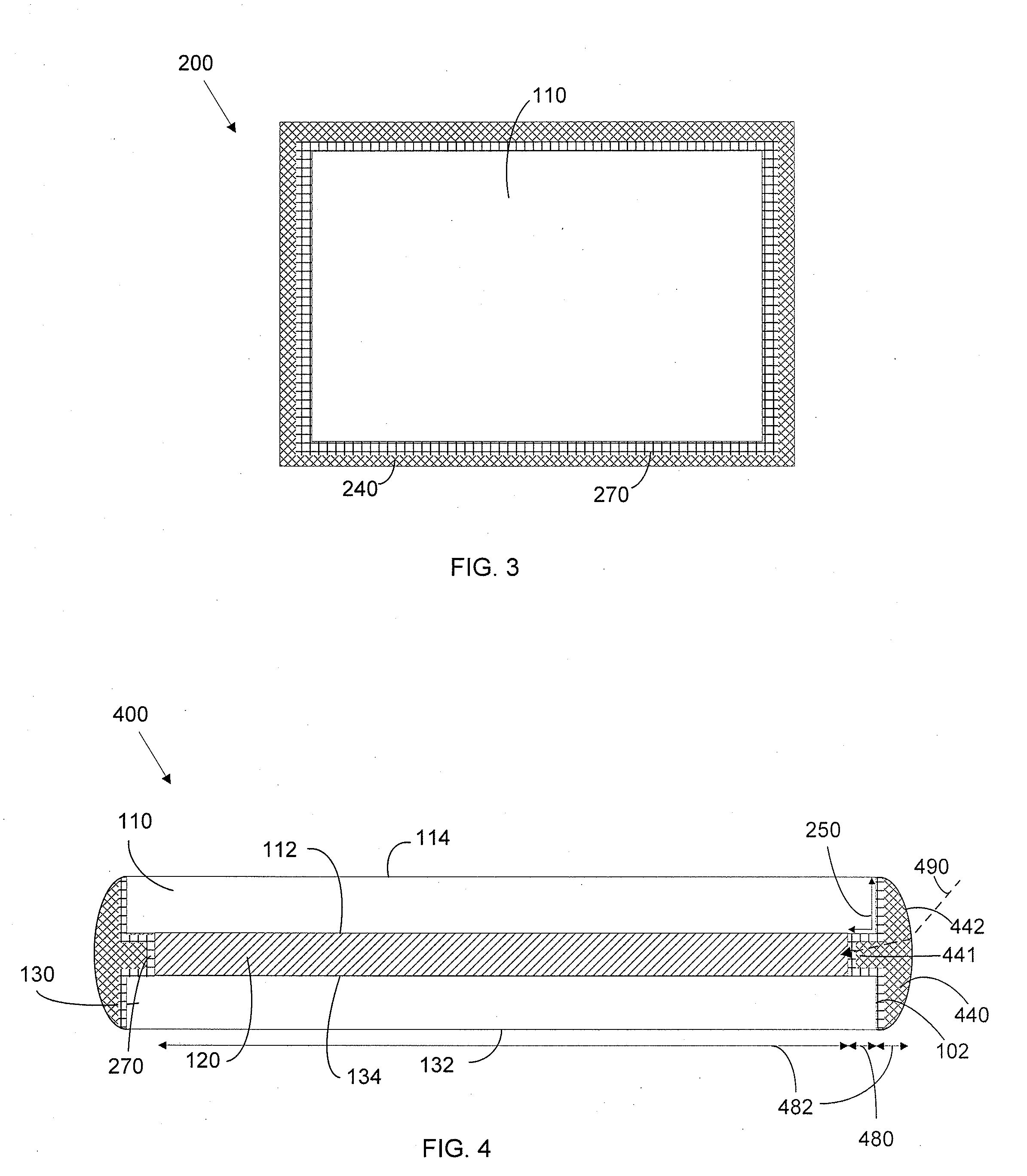
A solar module with a front support, a back support, and a photovoltaic active material located between the front and back supports. An electrically insulative light transmissive seal is located at the peripheral edges of the front support and back support to electrically isolate the active material from the outer surfaces of the solar module.

Description

FIELD OF THE INVENTION[0001]Embodiments of the invention relate to the field of photovoltaic (PV) power generation systems, and more particularly to a solar module and a manufacturing method thereof.BACKGROUND OF THE INVENTION[0002]A photovoltaic module or solar module, also known as a solar panel, is a device that converts the energy of sunlight directly into electricity by the photovoltaic effect. A solar module includes a plurality of photovoltaic cells, also known as solar cells, for example, crystalline silicon cells or thin-film cells. The photovoltaic cells convert light into electrical energy and are typically formed between front and back supports of the solar module. In thin-film modules, the photovoltaic cell can include sequential layers of various materials formed between the front support and the back support. Layers can include, for example, a barrier layer, a transparent conducting oxide (TCO) layer, a buffer layer, and an active material layer, all which can be depo...

Claims


Application Information

Patent Timeline
IPC IPC(8): H01L31/048
CPCH01L31/048Y02E10/50H01L31/0488
Inventor BULLER, BENYAMINMURPHY, STEVECOHEN, BRIAN
Owner FIRST SOLAR INC (US)
Learn More