
Airborne elevator apparatus

Inactive Publication Date: 2012-03-08
REDFORD DANIEL S
View PDF5 Cites 8 Cited by
  • Summary
  • Abstract
  • Description
  • Claims
  • Application Information

AI Technical Summary

Benefits of technology

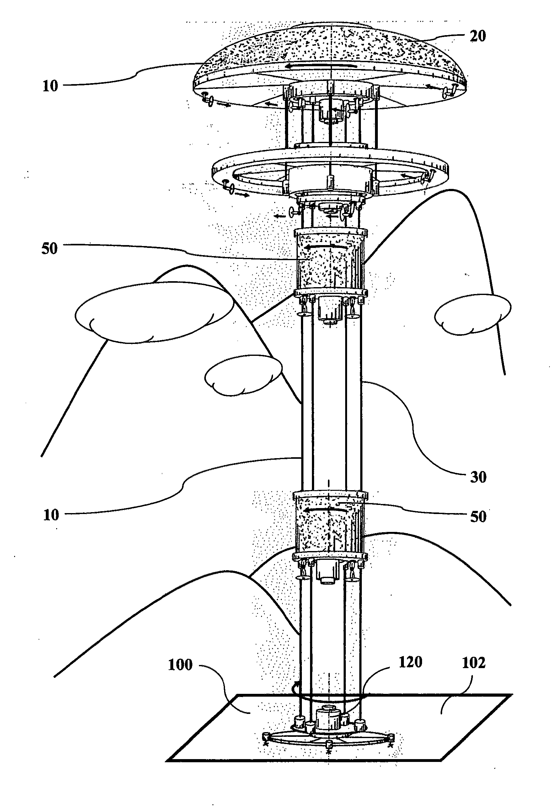
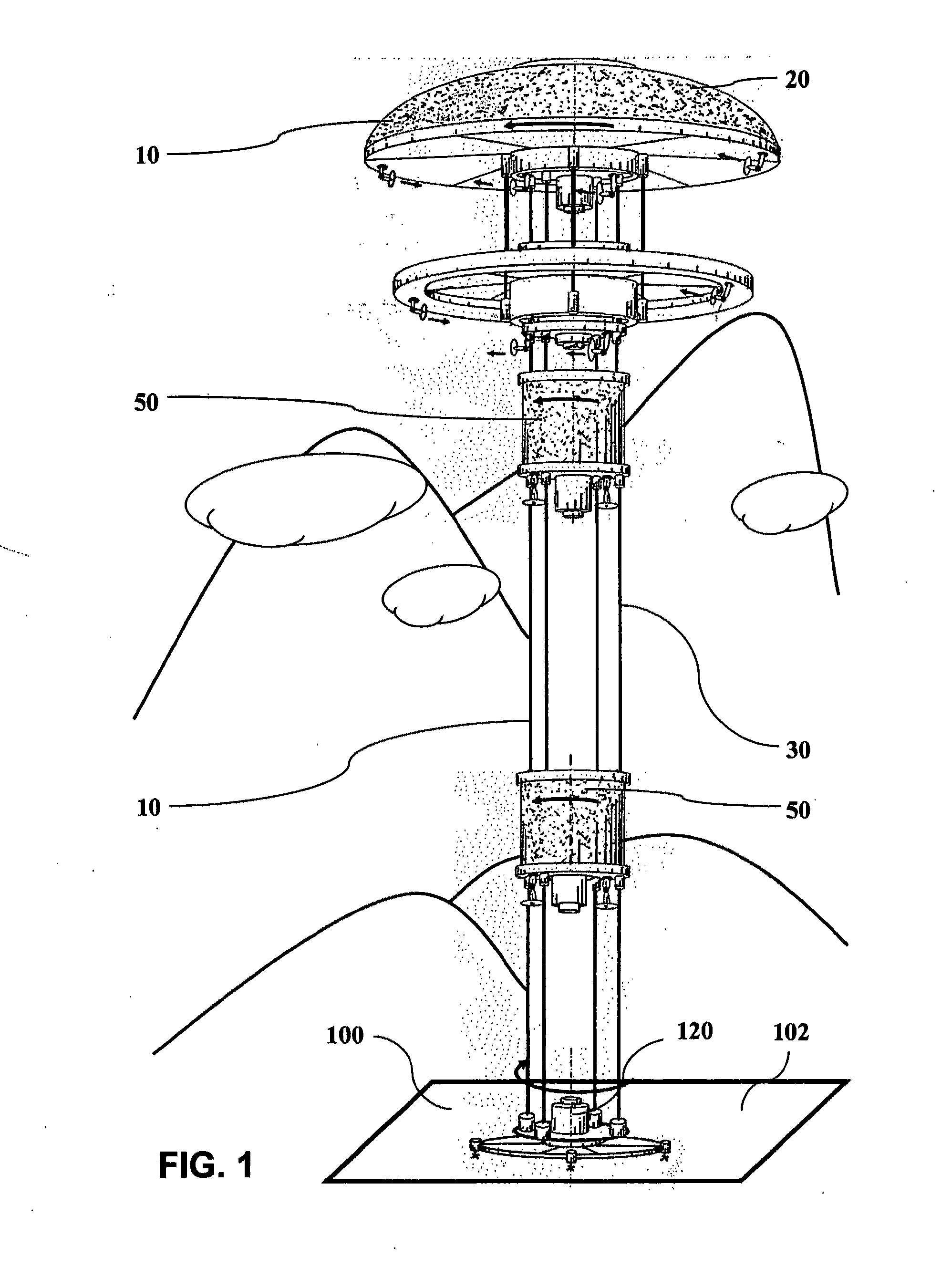
[0021]The apparatus and function of the present invention are directed to eliminate the limitations of current aerostats. The Airborne Elevator Apparatus is designed to separate a tether weight carrier from a service load carrier. This design feature allows the apparatus to deploy at the same time multiple service loads at different altitudes in the Earth's atmosphere without increasing the apparatus' tether weight.

Problems solved by technology

Also, a tethered aerostat is subject to wind migration; the wind will push away the aerostat from the ideal vertical deployment position.

Method used


Image

  • Airborne elevator apparatus
  • Airborne elevator apparatus
  • Airborne elevator apparatus

Examples


second embodiment

[0088]the present invention is shown in FIG. 6 and FIG. 7

[0089]FIG. 6 shows the second embodiment of the present invention where the airborne means 10 for positioning the apparatus in the Earth's atmosphere comprises an uppermost airborne canopy assembly 26 and a second airborne canopy assembly 29, filled with lighter than air gas and positioned at different altitudes in the atmosphere in order to share the load generated by the longer and implicitly heavier airborne cables 30.

[0090]FIG. 6 further shows:[0091]a first booster assembly 61 with a first airborne controller 151 deployed inside an uppermost airborne canopy assembly 26 on the apparatus' airborne cables 30,[0092]a second booster assembly 62 with a second airborne controller 152 deployed inside an uppermost airborne canopy-stabilizer sub-assembly 46 on the apparatus' airborne cables 30,[0093]a third booster assembly 63 with a third airborne controller 153 deployed below the canopy-stabilizer 46 on the apparatus' airborne cab...

third embodiment

[0108]the present invention is shown in FIG. 8

[0109]FIG. 8 shows the apparatus' main platform 130 further comprising four high-thrust swivel propellers 180 powerful enough to elevate and transport the main platform 130 to redeploy the apparatus to a different service area, while the apparatus is in operation.

[0110]FIG. 8 further shows two of the high-thrust propellers 180 configured as ascending / descending propellers and two configured as horizontal transport propellers.

[0111]FIG. 8 also shows an airborne command aircraft 200 remotely controlling the operation of apparatus' during its redeployment.


PUM


Abstract

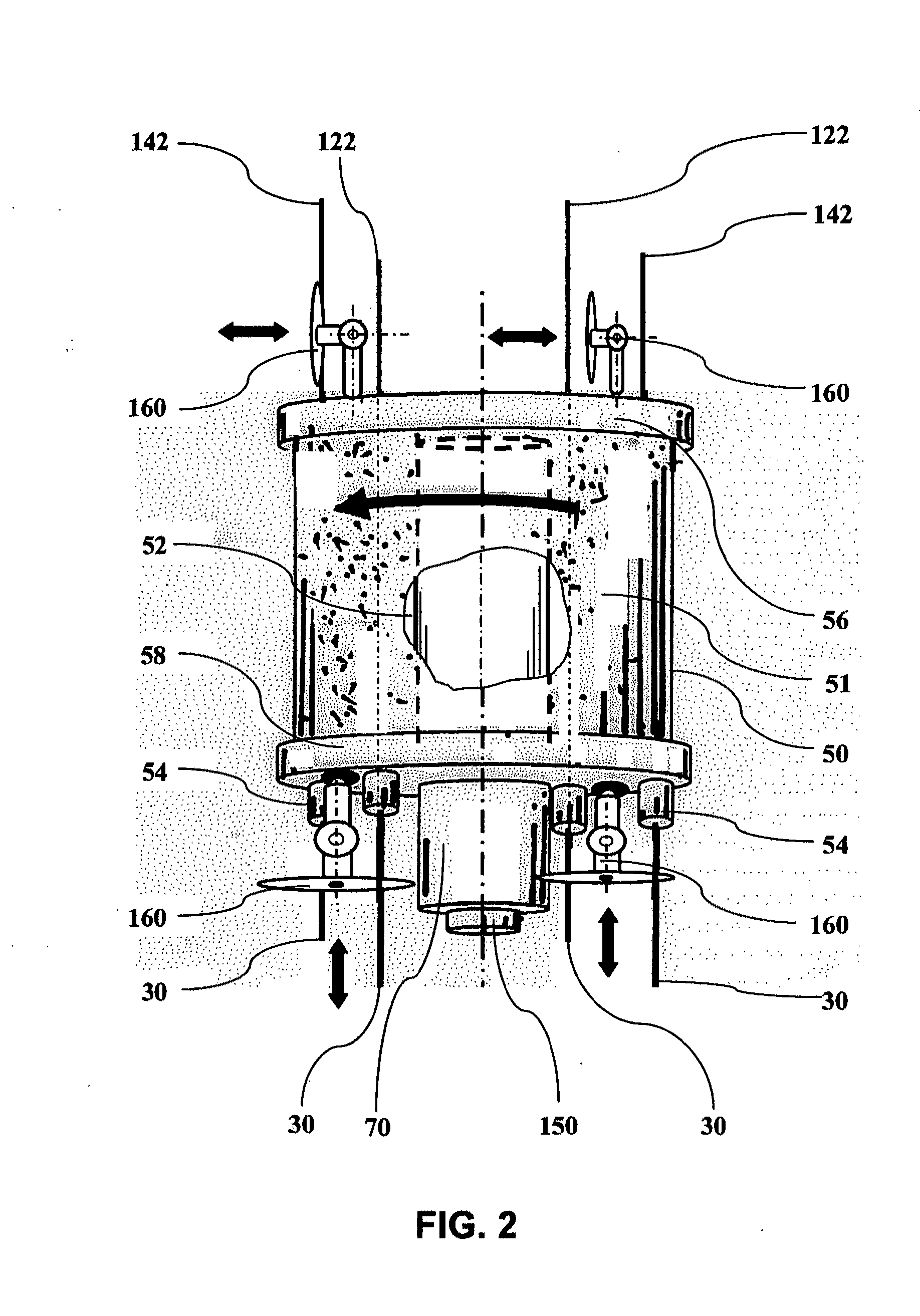
An Airborne Elevator Apparatus capable of deploying at the same time multiple service loads at different altitudes in the Earth's atmosphere by physically separating tether weight carrier function from the service load weight carrier function of a common aerostat. The tether weight carrier function is performed by at least one airborne canopy assembly (20) filled with lighter than air gas, which has enough lifting power to support its own weight and the weight of the attached airborne cables (30). The service load carrier function is performed by several airborne booster assemblies (51). Designed to glide on the apparatus's airborne cables (30), an airborne booster assembly (51) filled with lighter than air gas has enough lifting power to carry its own weight and the weight of a service load at altitudes below the uppermost canopy. For stability purposes, the apparatus is designed to rotate around its vertical axis.

Description

[0001]This application was originally filed as a Provisional Patent Application on Jun. 16, 2010 and was assigned Ser. No. 61 / 379,685.TECHNICAL FIELD[0002]The invention generally relates to the field of hybrid tethered aerostats, and more particularly to airborne elevators.BACKGROUND ART[0003]Contemporary interest in using tethered aerostats to carry and execute various surveillance and communication missions is growing. Unlike fixed-wing aircrafts or helicopters, these aerostats use helium or hydrogen to stay aloft. They are unmanned, inexpensive, and anchored to the ground by a tethering system that also provides power and communication.[0004]Webster's Dictionary defines the term “service load” as the “load a structure is expected to support under normal usage”.[0005]A tethered aerostat is designed to elevate and keep a service load at a predetermined deployment altitude in the Earth's atmosphere. Its lifting force should be sufficient to support its own weight, the weight of the ...

Claims


Application Information

Patent Timeline
IPC IPC(8): B64B1/50
CPCB64B1/50B64B1/30B64B1/06B64B1/66B64F1/14
Inventor REDFORD, DANIEL S.
Owner REDFORD DANIEL S
Learn More