High power-factor control circuit and method for switched mode power supply

a control circuit and power supply technology, applied in the direction of electroluminescent light sources, electric lighting sources, semiconductor lamp usage, etc., can solve the problems of not meeting the standards of conventional devices, smps for led lighting systems suffer from many limitations, and conventional led light bulbs often do not provide desirable efficiency in the utilization of ac power supplies, etc., to achieve high power factor and constant effect of led lighting system

Active Publication Date: 2012-03-08
BCD SHANGHAI MICRO ELECTRONICS CO LTD
View PDF5 Cites 59 Cited by
  • Summary
  • Abstract
  • Description
  • Claims
  • Application Information

AI Technical Summary

Benefits of technology

[0008]Embodiments of the present invention provide methods and circuits for an SMPS to provide a constant average output current at a high power factor. In some embodiments, the same SMPS controller IC can be used over a wide range of AC input voltages, such as 110V or 220V power supplies, without additional AC source selection circuits. Moreover, in some embodiments, the SMPS controller are also configured to provide constant average output current and high power factor in LED lighting systems with an adjustable dimmer circuit, in which the input AC input power is cut off during certain phase angles. These features can lower production cost of the LED lighting system and lead to even wider applications.

Problems solved by technology

However, conventional SMPS for LED lighting systems suffer from many limitations.
Moreover, unlike convention incandescent light bulbs, LEDs lighting devices do not behave like a purely resistive load in an AC circuit.
Therefore, conventional LED light bulbs often do not provide desirable efficiency in the utilization of the AC power supply.
Conventional devices often can not meet these standards.
Conventional LED lighting devices often can not accommodate a dimmer circuit, and can not provide the brightness adjustment capability.

Method used


Image

  • High power-factor control circuit and method for switched mode power supply
  • High power-factor control circuit and method for switched mode power supply
  • High power-factor control circuit and method for switched mode power supply

Examples


Embodiment Construction

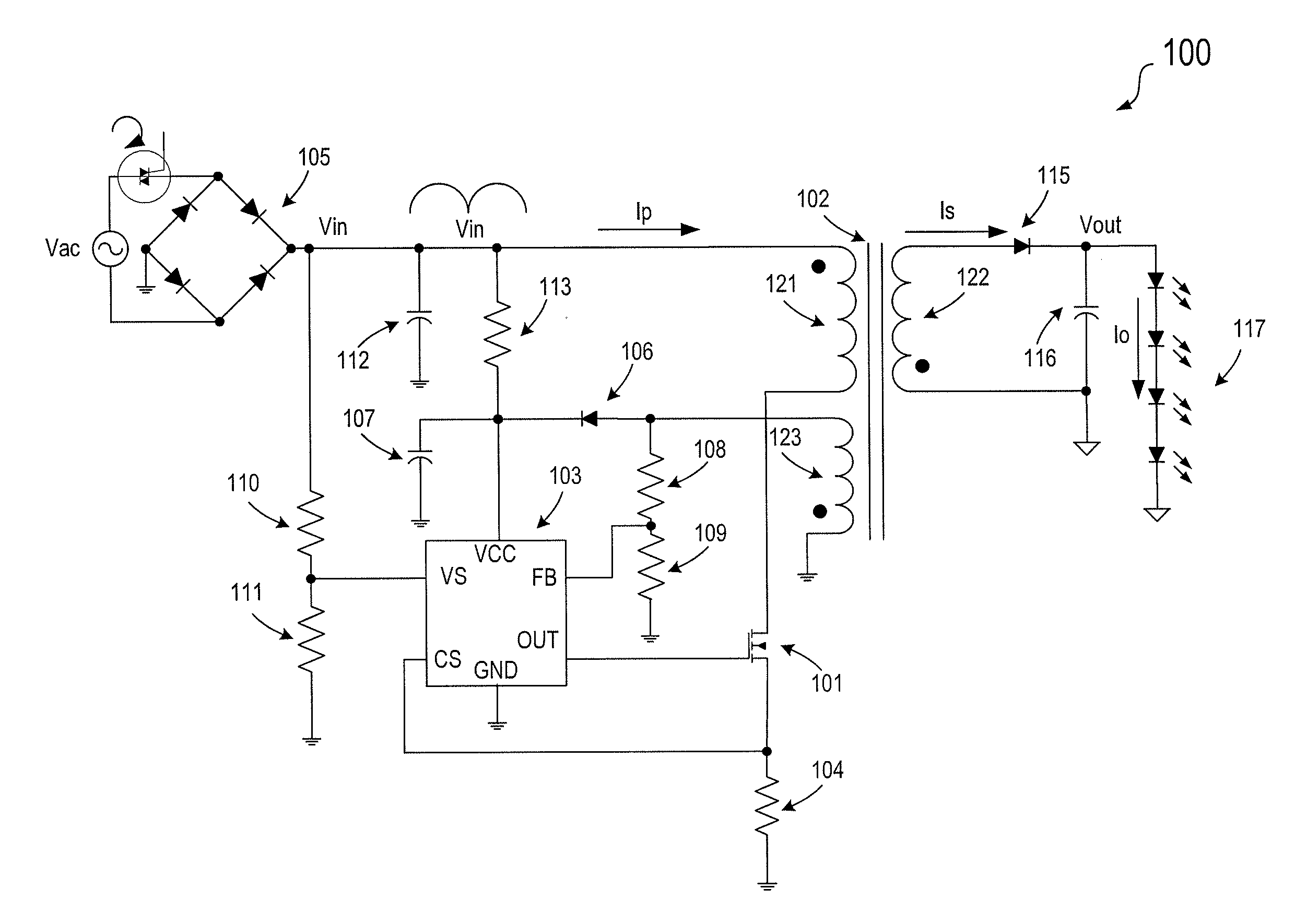
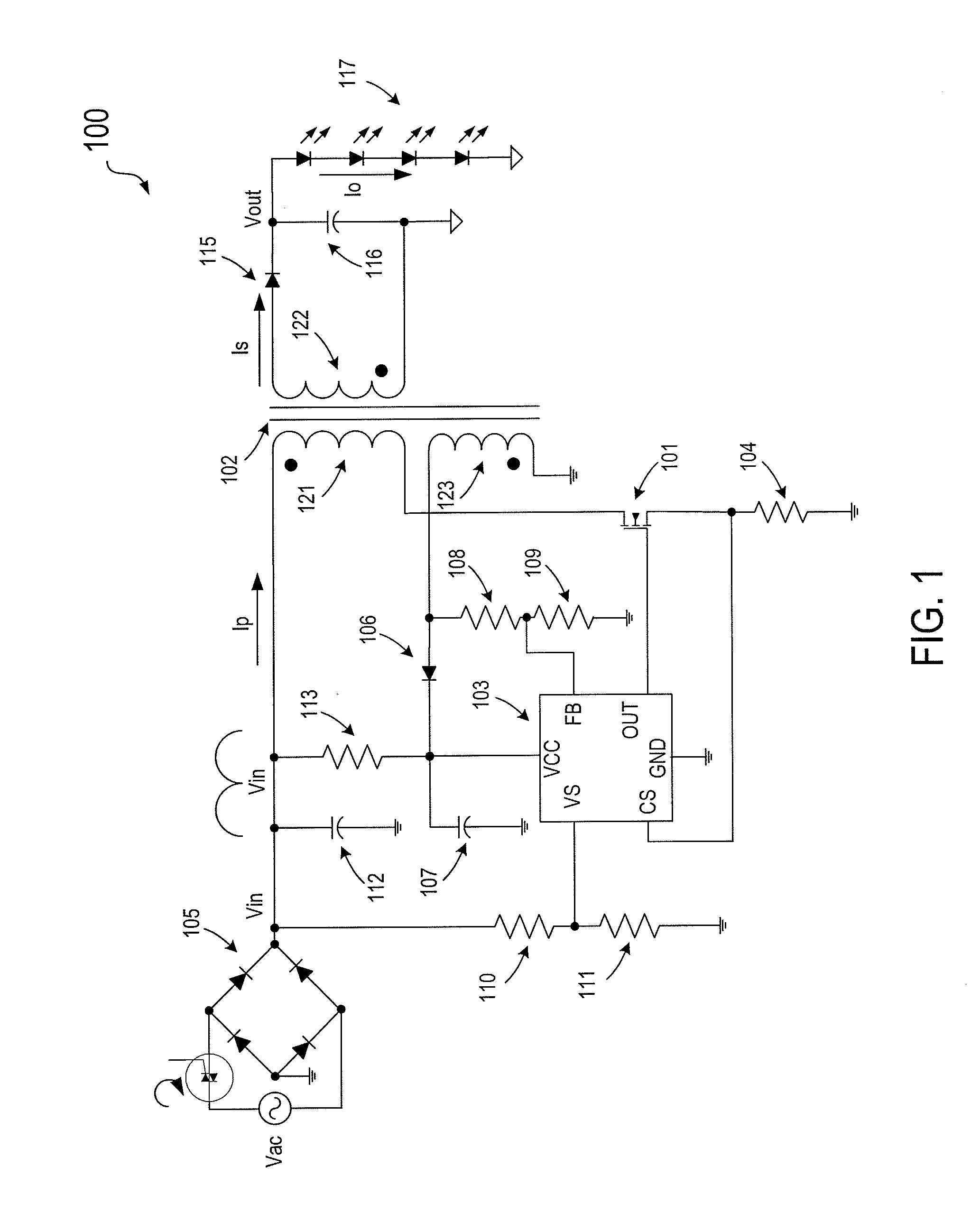
[0043]FIG. 1 is a simplified diagram illustrating a switch mode power supply (SMPS) 100 driving a string of light emitting diodes (LED) 117 according to an embodiment of the present invention. In this example, SMPS 100 includes in a flyback converter. However, other types of converter architecture can also be used. As shown in FIG. 1, SMPS 100 includes a transformer 102, a power supply controller 103, and a power switch 101. Transformer 102 has a primary winding 121, a secondary winding 122, and an auxiliary winding 123, in which the black dots denote terminals having the same polarity. Primary winding 121 receives a rectified input Vin from a rectifying circuit that includes a diode bridge 105 and rectifies an AC input voltage Vac. SMPS 100 provides an output Vout from secondary winding 122 through rectifying diode 115 and capacitor 116. As shown, the output terminal Vout also provides an output current Io to LED string 117.

[0044]In an embodiment, controller 103 is a single chip SM...


PUM


Abstract

A switch mode power supply (SMPS) system includes a rectifying circuit for coupling to an AC input voltage and a transformer having a primary winding for coupling to the rectifying circuit and a secondary winding coupled to the primary winding. The system also has a power switch coupled to the primary winding and a control circuit coupled to the power switch. The control circuit is configured to control current flow in the primary winding such that an envelop waveform formed by peak points of current pulses are in phase with the magnitude of the AC input voltage. Moreover, the SMPS system is configured to provide a constant average output current.

Description

CROSS-REFERENCES TO RELATED APPLICATIONS[0001]This application claims benefit and priority of Chinese Patent Application No. 201010275190.X, filed Sep. 6, 2010, commonly owned and incorporated herein by reference in its entirety for all purposes.BACKGROUND OF THE INVENTION[0002]The present invention relates generally to switch mode power supply (SMPS) systems. More particularly, embodiments of the invention relate to methods and circuits for controlling and improving the power factor of SMPS systems.[0003]Switch mode power supply (SMPS) systems have many advantages over convention linear regulated power supplies. These advantages include smaller volume, better stability, and higher power efficiency. As a result, SMPS has found wide spread applications, such as televisions, set-top boxes, and video recorders, portable telephone chargers, personal digital assistants (PDAs), and even certain automated tooth brushes. In recently years, as light emitting diode (LED) technologies are beco...

Claims


Application Information

Patent Timeline
IPC IPC(8): H05B41/282H05B44/00
CPCH02M1/4258Y02B20/347Y02B70/126H05B33/0818Y02B20/30Y02B70/10H05B45/385H05B45/3725H02M3/33507
Inventor ZHU, SHIHAICHEN, ZEQIANGREN, XUEGANGZHU, YAJIANG
Owner BCD SHANGHAI MICRO ELECTRONICS CO LTD
Why Eureka
Try Eureka