Composite transformer

a transformer and composite technology, applied in the direction of transformer/inductance magnetic core, fixed transformer, inductance, etc., can solve the problems of difficult to increase the number of windings to be arranged in parallel, magnetic energy loss occurs, etc., and achieve the effect of avoiding the increase of the number of parts

Active Publication Date: 2012-03-08
HONDA MOTOR CO LTD
View PDF7 Cites 49 Cited by
  • Summary
  • Abstract
  • Description
  • Claims
  • Application Information

AI Technical Summary

Benefits of technology

[0092](5) Since the transformer core 20 is formed with the two transformer-core members 21, the number of parts constituting the transformer core 20 is not changed even when the number of windings wound around the transformer-core legs 23 is increased. That is, it is possible to avoid increase in the number of parts even when the number of windings increases.
[0093]The present invention is not limited to the composite transformer 1a according to first embodiment. For example, the present invention can also include the composite transformer 1b according to the second embodiment, which is a three-phase composite transformer having three windings. The composite transformer 1b according to the second embodiment is explained below with reference to FIGS. 5 to 10.
[0094]As illustrated in FIG. 5, the composite transformer 1b according to the second embodiment is a three-phase composite transformer which includes three windings 50, a transformer core 60, three inductor cores 70, and a magnetic-insulation sheet 80 and in which a transformer and inductors are integrally arranged. That is, the number of the windings 50 in the composite transformer 1b according to the second embodiment is greater than the number of the windings 10 in the...

Problems solved by technology

Further, if an attempt is made to arrange more than two windings around the central core leg, many physical constraints limit the layout, so that it is difficult to increase the number of windings to be arranged in parallel.
In addition, in the c...

Method used


Image

  • Composite transformer
  • Composite transformer
  • Composite transformer

Examples


first embodiment

1. First Embodiment

1.1 Composite Transformer 1a

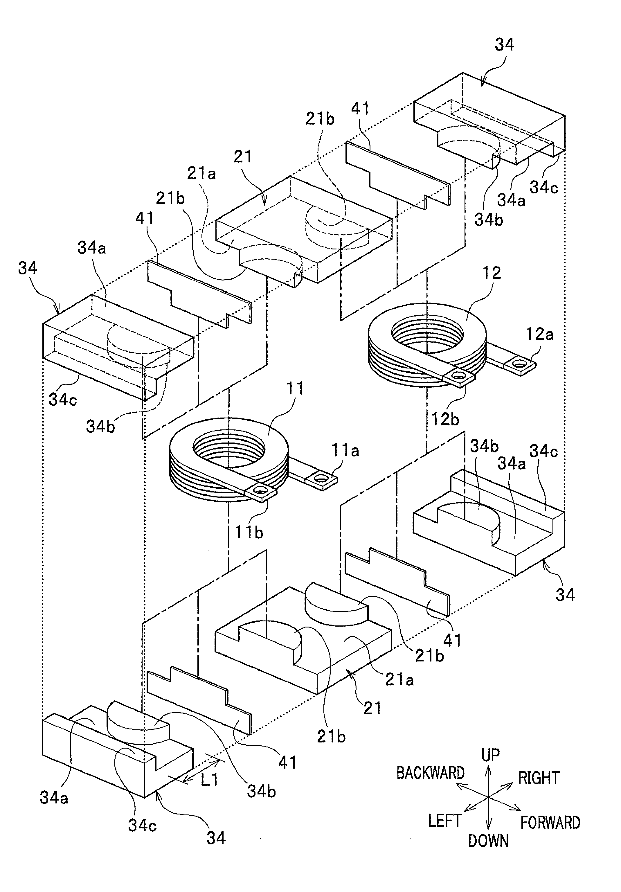
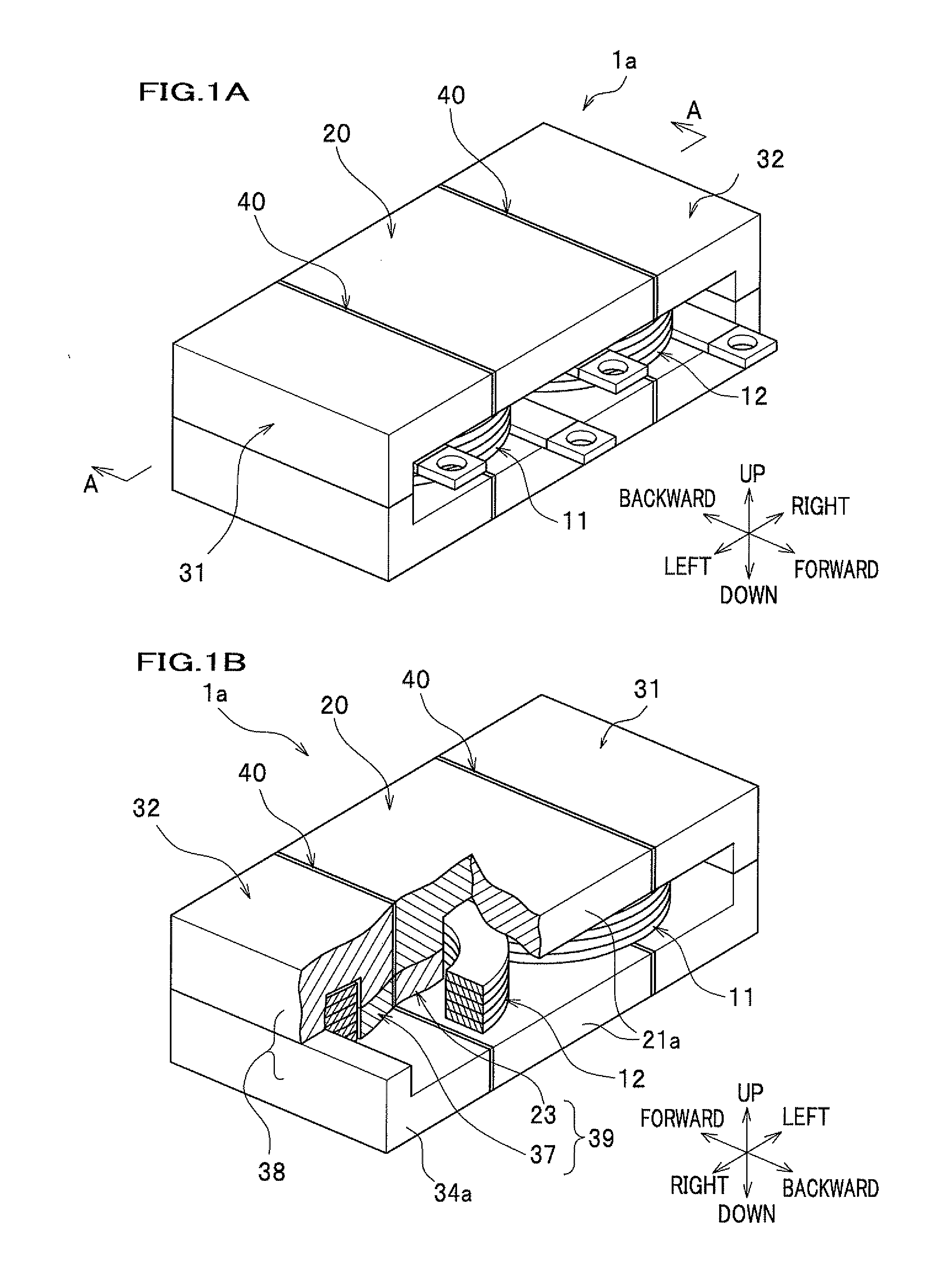
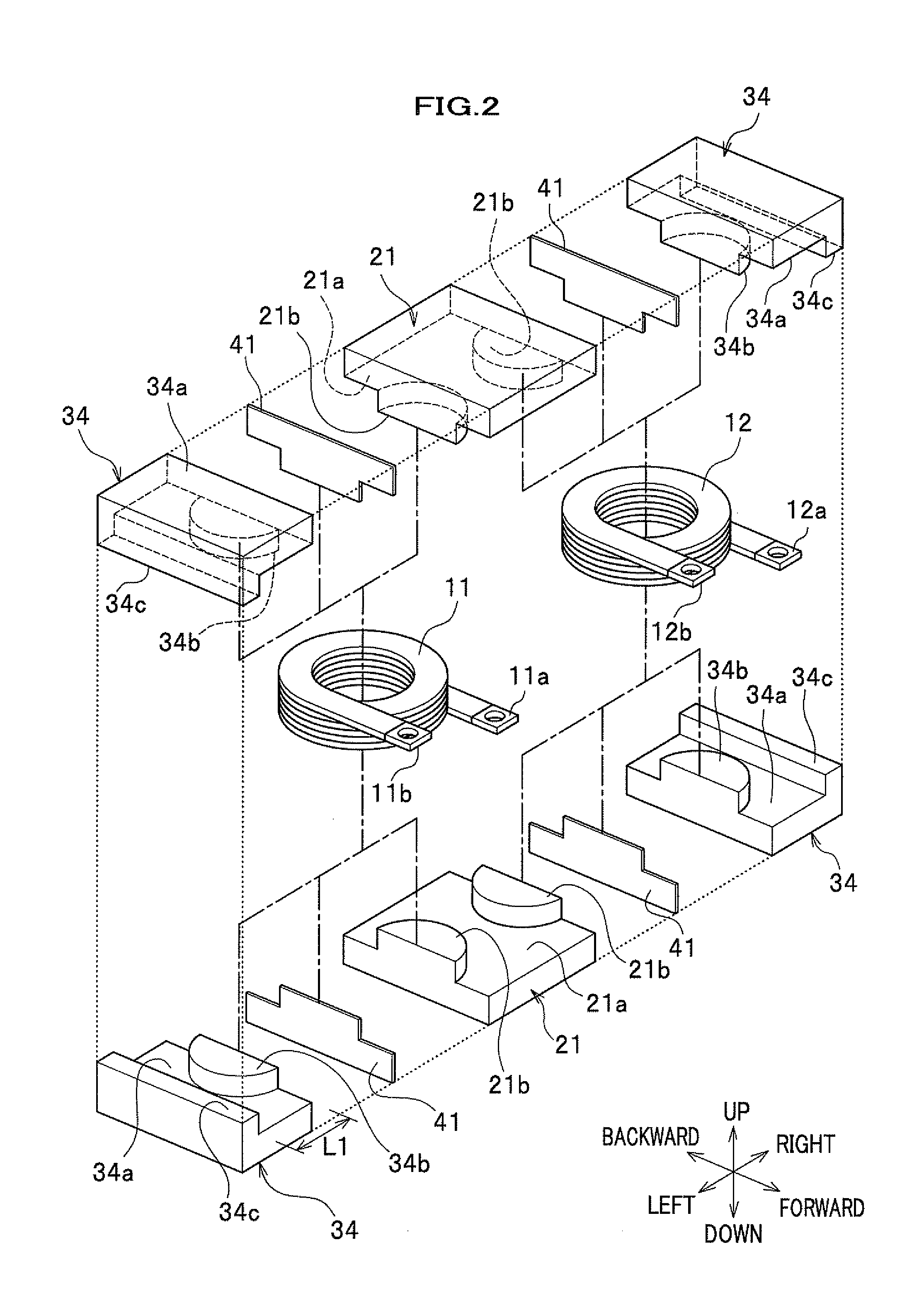
[0042]As illustrated in FIGS. 1A and 1B, the composite transformer 1a according to the first embodiment is a two-phase composite transformer which includes two windings 10 and in which a transformer and inductors are integrally arranged. In FIGS. 1A and 1B, the first winding constituting the two windings 10 and being arranged on the left side (viewed from front) is denoted by the reference 11, and the second winding constituting the two windings 10 and being arranged on the right side (viewed from front) is denoted by the reference 12.

[0043]As illustrated in FIGS. 1A, 1B, and 2, the composite transformer 1a is constituted by the two windings 10, a transformer core 20 containing and supporting the two windings 10, two inductor cores 30 arranged on both sides of the transformer core 20, and two magnetic-insulation sheets 40 arranged between the transformer core 20 and the inductor cores 30.

1.2 Windings 10

[0044]The windings 10 are members...

second embodiment

2. Second Embodiment

[0093]The present invention is not limited to the composite transformer 1a according to first embodiment. For example, the present invention can also include the composite transformer 1b according to the second embodiment, which is a three-phase composite transformer having three windings. The composite transformer 1b according to the second embodiment is explained below with reference to FIGS. 5 to 10.

2.1 Composite Transformer 1b

[0094]As illustrated in FIG. 5, the composite transformer 1b according to the second embodiment is a three-phase composite transformer which includes three windings 50, a transformer core 60, three inductor cores 70, and a magnetic-insulation sheet 80 and in which a transformer and inductors are integrally arranged. That is, the number of the windings 50 in the composite transformer 1b according to the second embodiment is greater than the number of the windings 10 in the composite transformer 1a according to the first embodiment.

[0095]...

examples 1

3.1 Concrete Examples 1

[0128]In each of the concrete examples 1, the composite transformer 1a according to the first embodiment of the present invention is arranged in a DC-DC converter, and the applied voltage is boosted by turning on and off a switching element in the DC-DC converter. The composite transformers in the concrete examples 1 respectively have different numbers of turns, and the volumes of the composite transformers have been measured. In addition, the values of the copper loss and the core loss (as the losses in the magnetic parts) in the composite transformers in the concrete examples 1 have been calculated for cases in which a predetermined voltage is applied to and a predetermined amount of current is passed through the composite transformers. The calculation conditions such as the applied voltage are indicated in Table 1.

TABLE 1OutputRippleAppliedInput CurrentPowerSwitchingCurrentVoltage (Vin)(Iin)(Pout)Frequency (fsw)(Ipp)70 V150 A10.5 kW45 kHz17 A p-p

[0129]In ad...


PUM


Abstract

A composite transformer includes: a transformer core including transformer-core legs; inductor cores including inductor-core legs; windings wound around the transformer-core legs and the inductor-core legs; the transformer core includes a pair of transformer bases connected to both ends of each of the transformer-core legs, and allows formation of closed magnetic circuits in the transformer core; each of the inductor cores includes one of the inductor-core legs, an outer core leg, and a pair of inductor bases connected to both ends of the one of the inductor-core legs and both ends of the outer core leg, and allows formation of a closed magnetic circuit in each inductor core; and the windings are wound in such directions that the magnetic fluxes produced in the transformer-core legs cancel each other in the closed magnetic circuits in the transformer core whichever of the windings is energized.

Description

CROSS REFERENCE TO RELATED APPLICATION[0001]This application claims the foreign priority benefit under 35 U.S.C. §119 of Japanese Patent Application No. 2010-197415, filed on Sep. 3, 2010, the disclosure of which is incorporated herein by reference.BACKGROUND OF THE INVENTION[0002]1. Field of the Invention[0003]The present invention relates to a composite transformer (a combined type transformer), and more particularly to a composite transformer (a combined type transformer) which is downsized and causes a small magnetic energy loss.[0004]2. Description of the Related Art[0005]Conventionally, in the field of the electric-power conversion circuits such as DC-DC converters, various inventions have been made. (DC stands for direct current.)[0006]For example, Japanese Patent Laid-open No. 2005-224058 discloses a DC-DC converter using a magnetic-field canceling transformer in which a plurality of windings are arranged so that the magnetic fluxes produced by the plurality of windings canc...

Claims


Application Information

Patent Timeline
IPC IPC(8): H01F27/28H01F27/29H01F27/24
CPCH01F27/2828H01F30/06H01F27/38H01F27/365H01F27/36H01F27/366
Inventor NAGANO, MASAOHASHINO, SATOSHIHIRAKAWA, MITSUAKI
Owner HONDA MOTOR CO LTD
Why Eureka
Try Eureka