Radio Controlled Step Dimmer Control for Fluorescent Light Fixtures

a dimmer control and radio control technology, applied in the direction of electric controllers, ignition automatic control, instruments, etc., can solve the problems of limiting the usability of dimmer control, difficult to achieve satisfactory preheat and ignition, and unsatisfactory systems, etc., to achieve effective and cost-effective

Inactive Publication Date: 2012-03-08
PAUL JEFFREY M
View PDF11 Cites 20 Cited by
  • Summary
  • Abstract
  • Description
  • Claims
  • Application Information

AI Technical Summary

Benefits of technology

[0020]The method and apparatus of the present invention, including a programmable wireless radio frequency transmitter to control the three level step dimming ballast ...

Problems solved by technology

Such systems have been unsatisfactory, however, for it has been difficult to achieve satisfactory preheat and ignition under low-voltage co...

Method used


Image

  • Radio Controlled Step Dimmer Control for Fluorescent Light Fixtures
  • Radio Controlled Step Dimmer Control for Fluorescent Light Fixtures
  • Radio Controlled Step Dimmer Control for Fluorescent Light Fixtures

Examples


Embodiment Construction

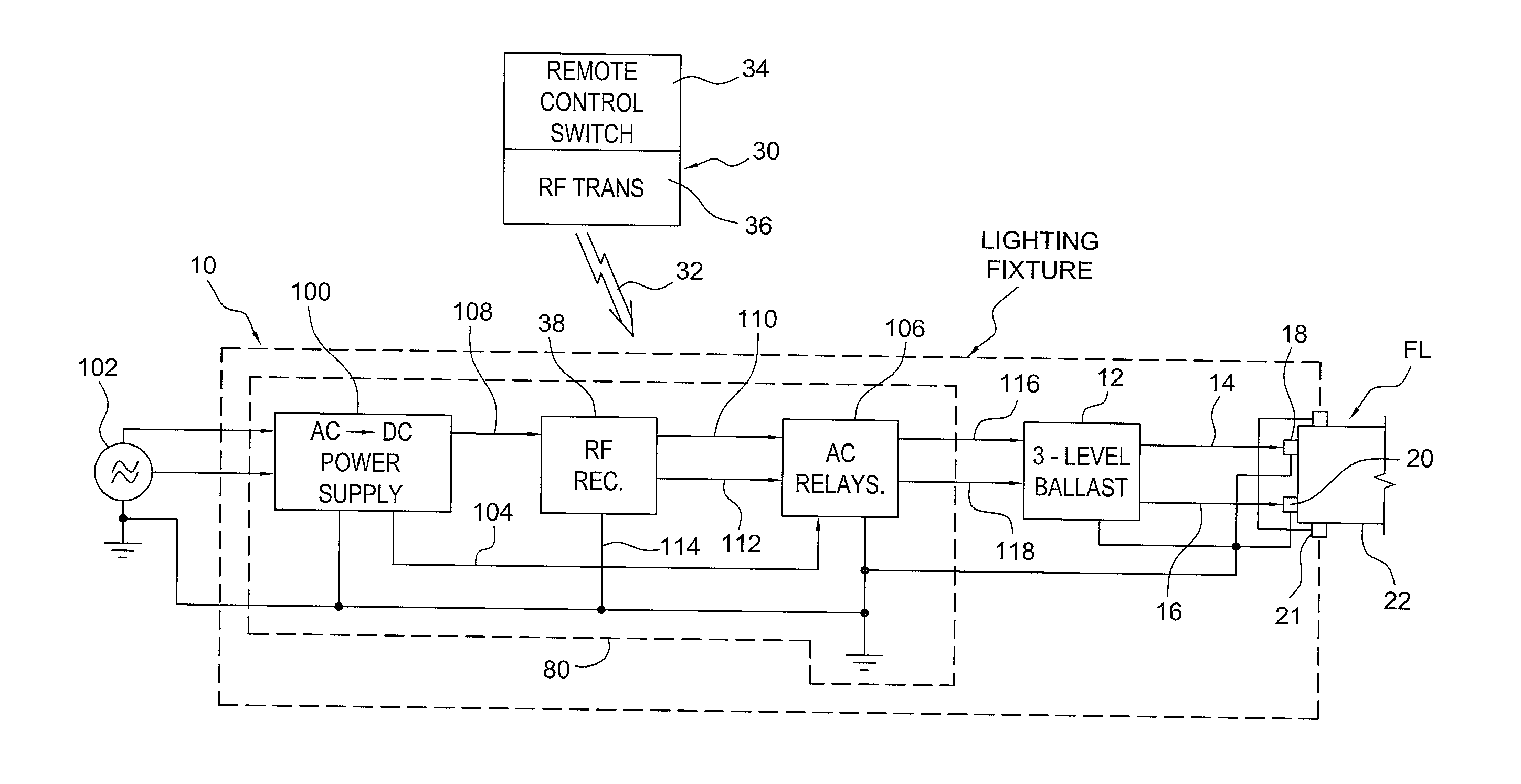
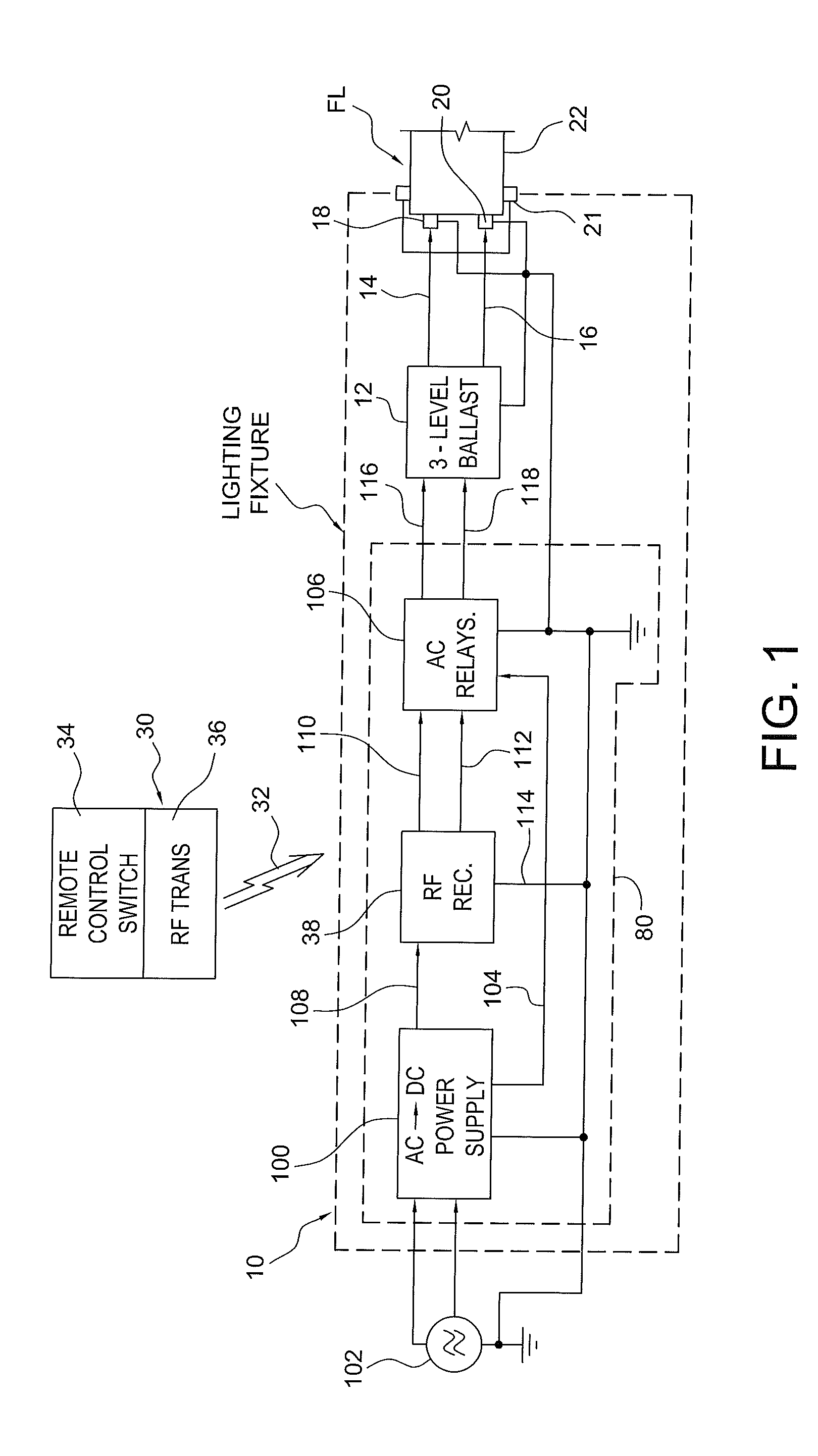
[0032]Turning now to a more detailed description of the present invention as illustrated in FIGS. 1-12, a controllable and dimmable florescent lighting fixture 10 is diagrammatically illustrated in FIG. 1 as including a commercially available multilevel florescent lamp ballast 12, in this embodiment a three-level ballast such as the GE® LFL UltraMax™ Step Dimming Electronic Ballast #73231-GE332Max90-S60 ballast available from General Electric, two outputs 14 and 16 of which are connected, in this case, to corresponding contacts 18 and 20, respectively, of a three-way florescent lamp 22 by way of a conventional three-way lamp socket diagrammatically illustrated at 21. Output voltages on either output 14 or 16, or both, control the illumination level of the fluorescent lamp, in known manner.

[0033]Although a single fluorescent lamp 22 is illustrated in FIG. 1, it is to be understood that the ballast may be connected to, and control, multiple lamps in a fixture 10, and that the fixture ...


PUM


Abstract

A lighting system includes a remotely controllable step dimmer for controlling one or more fluorescent light fixtures with a fixed or transportable light controller with a wireless signal transmitter and at least a first control input or switch configured for manual actuation by a lighting system user. The light controller transmitter is configured to wirelessly transmit one of a plurality of uniquely encoded or modulated lighting control signals to at least a first light fixture's wireless receiver.

Description

[0001]This application claims the benefit of U.S. Provisional Application No. 61 / 333,699, Filed May 11, 2011, of Jeffrey M. Paul, the entire disclosure of which is incorporated herein by reference.BACKGROUND OF THE INVENTION[0002]1. Field of the Invention[0003]The present invention relates to control circuits for use with illumination sources such as fluorescent light fixtures, and more particularly to a programmable radio frequency transmitter to control a three-level, step-dimming ballast circuit configured for use with a fluorescent lighting fixture including fluorescent lamps, linear bulbs or tubes.[0004]2. Discussion of the Prior Art[0005]Fluorescent lighting has, in the past, been controlled by hard wired switches, where an on-off switch controls a ballast circuit in each light fixture which, in turn, energizes and controls one or more fluorescent light tubes. This method for controlling fluorescent lighting fixtures provided only on-off options for control, however, so a need...

Claims


Application Information

Patent Timeline
IPC IPC(8): G05B11/01
CPCH05B41/40H05B37/0272H05B47/19
Inventor PAUL, JEFFREY M.
Owner PAUL JEFFREY M
Why Eureka
Try Eureka