Light emitting device, surface light source, and liquid crystal display apparatus

a technology of liquid crystal display and light source, which is applied in the direction of luminescence, lighting and heating apparatus, instruments, etc., can solve the problems of difficult cost reduction, and achieve the effect of reducing the anisotropy of light from the light sour

Active Publication Date: 2012-03-08
SHENZHEN JUFEI OPTOELECTRONICS CO LTD
View PDF7 Cites 15 Cited by
  • Summary
  • Abstract
  • Description
  • Claims
  • Application Information

AI Technical Summary

Benefits of technology

[0015]According to the above-mentioned configuration, the refractive power of the lens in the length direction of the light emitting surface of the light source is greater than that in the direction orthogonal to the length direction, and thus the anisotropy of the light from the light source is reduced by the lens. Therefore, according to the present invention, it is possible to make the light from a light source having a non-symmetric light emitting surface uniform in the circumferential direction and radiate it while using a relatively small lens.

Problems solved by technology

Although the use of such a large number of LEDs may allow uniform brightness on the front surface of the backlight, the need for a large number of LEDs makes it difficult to reduce the cost, which is a problem.

Method used


Image

  • Light emitting device, surface light source, and liquid crystal display apparatus
  • Light emitting device, surface light source, and liquid crystal display apparatus
  • Light emitting device, surface light source, and liquid crystal display apparatus

Examples


embodiment 1

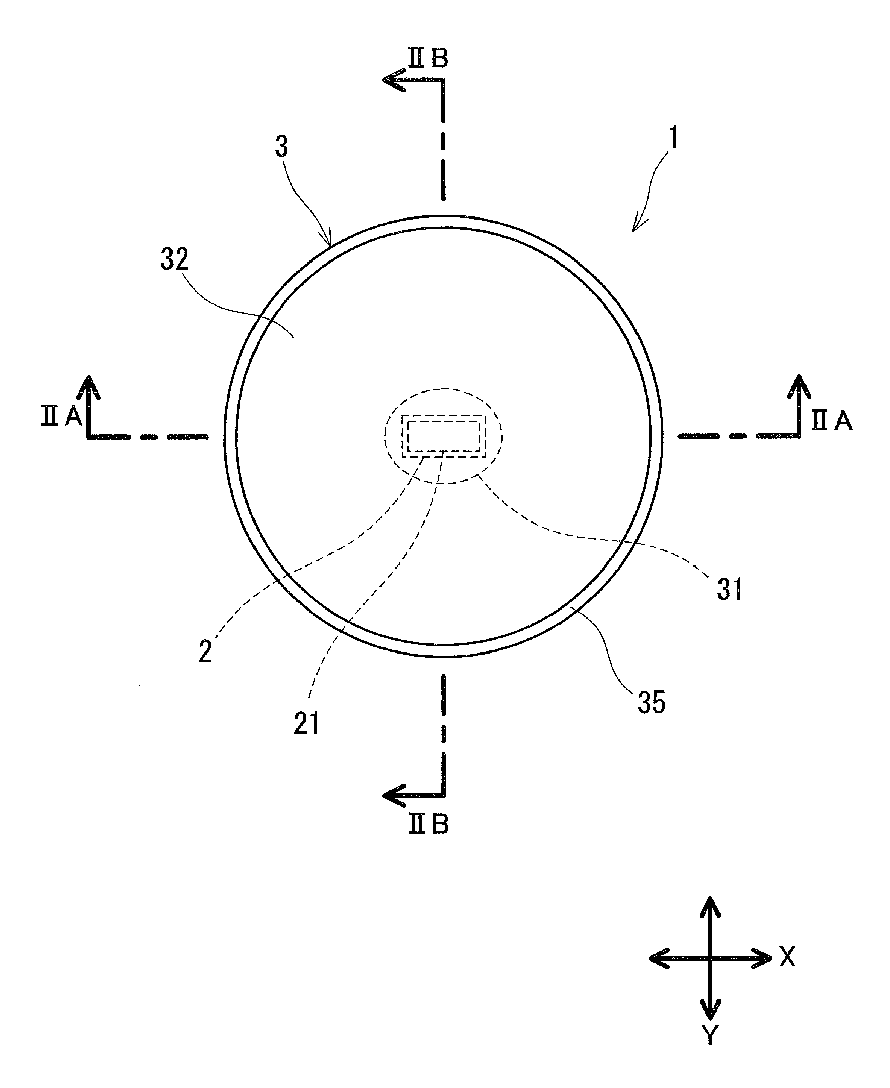
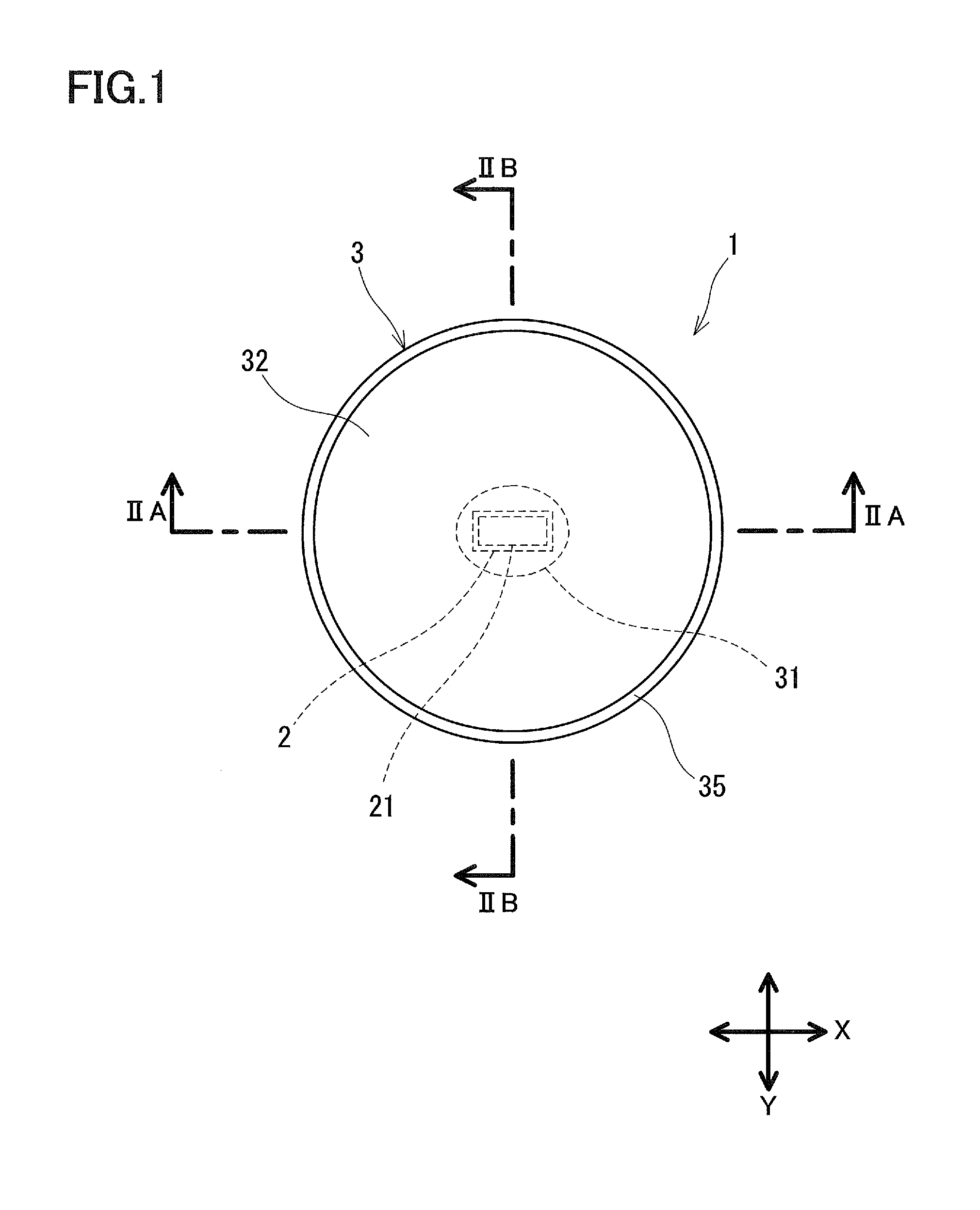
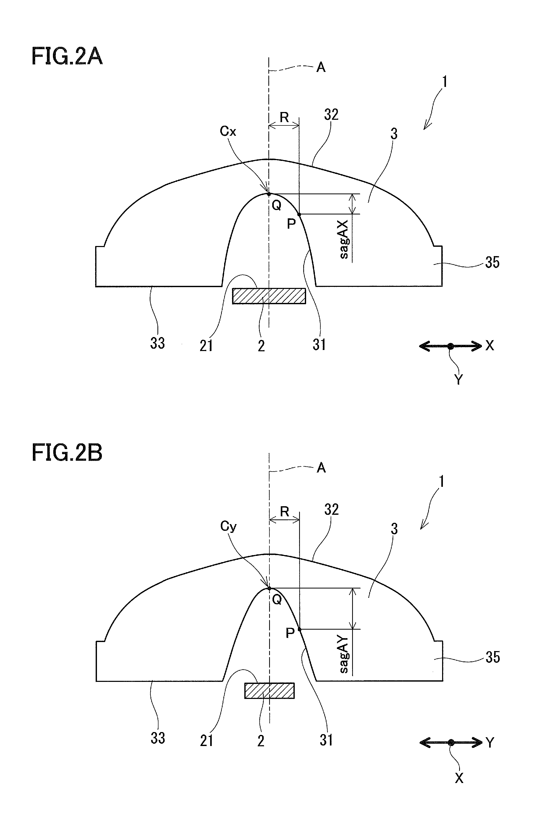
[0047]FIG. 1, and FIGS. 2A and 2B each show a light emitting device 1 according to Embodiment 1 of the present invention. The light emitting device 1, for example, is configured to radiate light onto the illumination target surface in a substantially circular manner, with an optical axis A being at the center, and is provided with a light source 2, and a lens 3 that expands the light from the light source 2 radially. That is, the directionality of the light from the light source 2 is widened by the lens 3, thereby allowing a wide range of the illumination target surface to be illuminated, with the optical axis A being at the center. The illuminance distribution on the illumination target surface reaches its peak on the optical axis A, and almost monotonically decreases toward the circumference.

[0048]The light source 2 has a light emitting surface 21 extending in a first direction orthogonal to the optical axis A. Thus, the light source 2 radiates anisotropic light. In this descripti...

modified example

[0064]The light exit surface 32 that is rotationally symmetric with respect to the optical axis A is not necessarily convex over the entire area. For example, it may have a portion with a concave surface in the vicinity of the optical axis and a portion with a convex surface in the circumference thereof. Alternatively, the light exit surface 32 may have a portion with a flat surface in the vicinity of the optical axis.

[0065]In this embodiment, only the light entrance surface 31 includes an anamorphic aspherical curved surface. However, in order to obtain a lens having a greater refractive power in the Y direction than in the X direction, at least one of the light entrance surface 31 and the light exit surface 32 should include an anamorphic aspherical curved surface.

[0066]For example, as shown in FIG. 5A, a configuration in which the light entrance surface 31 is a continuous concave surface that is rotationally symmetric with respect to the optical axis A, and the light exit surface...

example 1

[0072]Example 1 is a design example intended to widen the directionality of the light from the light source 2 by employing, as the light source 2, a general-purpose LED in which the light emitting surface 21 has a length of 2.60 mm in the X direction and a width of 1.00 mm in the Y direction. In Example 1, the lens 3 has an effective diameter of 15 mm. Table 1 shows specific numerical values for Example 1.

TABLE 1RsagAX (mm)RsagAY (mm)RsagB (mm)0.000.0000.000.0000.000.0000.05−0.0020.05−0.0030.100.0000.10−0.0100.10−0.0130.20−0.0020.15−0.0220.15−0.0300.30−0.0060.20−0.0400.20−0.0540.40−0.0130.25−0.0620.25−0.0840.50−0.0230.30−0.0900.30−0.1200.60−0.0370.35−0.1220.35−0.1640.70−0.0530.40−0.1590.40−0.2140.80−0.0720.45−0.2010.45−0.2700.90−0.0930.50−0.2480.50−0.3331.00−0.1160.55−0.3000.55−0.4021.10−0.1410.60−0.3570.60−0.4781.20−0.1660.65−0.4180.65−0.5601.30−0.1930.70−0.4850.70−0.6481.40−0.2190.75−0.5560.75−0.7431.50−0.2460.80−0.6320.80−0.8431.60−0.2730.85−0.7120.85−0.9501.70−0.3000.90−0.7970.9...


PUM


Abstract

A light emitting device (1) is configured to radiate light with an optical axis A at the center, and is provided with a light source (2), and a lens (3) that radially expands the light from light source (2). The light source (2) has a light emitting surface (21) extending in an X direction orthogonal to the optical axis A. The lens (3) is configured to have a greater refractive power in a Y direction orthogonal to the X direction than in the X direction. For example, the lens (3) has a light entrance surface (31) including an anamorphic curved surface with different curve forms between the X direction and the Y direction.

Description

TECHNICAL FIELD[0001]The present invention relates to a light emitting device that widens the directionality of light from a light source such as a light emitting diode (hereinafter, simply referred to as an “LED”). The present invention further relates to a surface light source provided with a plurality of light emitting devices, and to a liquid crystal display apparatus provided with this surface light source disposed behind a liquid crystal panel as a backlight.BACKGROUND ART[0002]Conventionally, in a backlight for large-sized liquid crystal display apparatuses, a number of cold cathode tubes are disposed immediately below a liquid crystal panel to be used with other members such as a diffusing plate and a reflecting plate. In recent years, LEDs have been used in common as light sources for backlights. LEDs are expected to serve as low-power light sources to replace fluorescent lamps, due to the recent improvement in their efficiency. When LEDs are used as light sources in a liqu...

Claims


Application Information

Patent Timeline
Patent Type & Authority Applications(United States)
IPC IPC(8): G02F1/13357F21K2/00F21V7/00F21V5/04
CPCG02B13/08H01L33/58G02F1/133603
Inventor IIYAMA, TOMOKOYOSHIKAWA, MOTONOBUMATSUKI, DAIZABURO
Owner SHENZHEN JUFEI OPTOELECTRONICS CO LTD
Why Eureka
Try Eureka