Polarization conversion system and stereoscopic projection system employing same

a stereoscopic projection and polarization technology, applied in the field of stereoscopic projection systems, can solve the problems of inconvenient periodic replacement of the battery of the liquid crystal shutter glasses, the bulky and heavy nature of the approach, and the inability to adjust the polarization and polarization parameters, etc., and achieve good imaging quality.

Inactive Publication Date: 2012-03-08
DELTA ELECTRONICS INC
View PDF8 Cites 36 Cited by
  • Summary
  • Abstract
  • Description
  • Claims
  • Application Information

AI Technical Summary

Benefits of technology

[0009]The present invention also provides a stereoscopic projection system having a polarization conversion system and a relay lens group for splitting a non-polar...

Problems solved by technology

However, this approach has some drawbacks.
For example, the liquid crystal shutter glasses are bulky and heavy.
In addition, it is inconvenient to periodically replace the battery of the liquid crystal shutter glasses.
Consequently, ...

Method used


Image

  • Polarization conversion system and stereoscopic projection system employing same
  • Polarization conversion system and stereoscopic projection system employing same
  • Polarization conversion system and stereoscopic projection system employing same

Examples


first embodiment

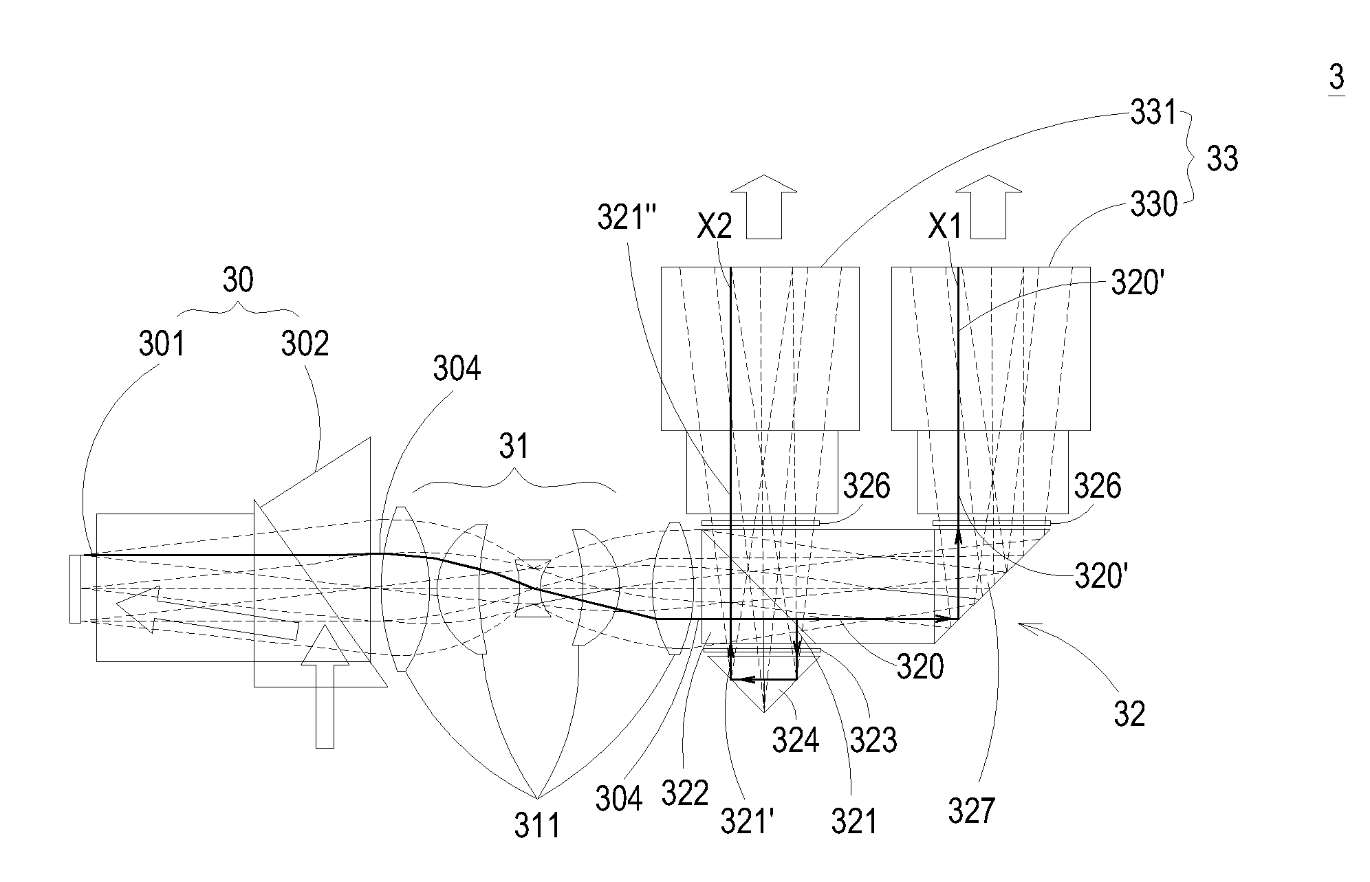
[0022]FIG. 3A schematically illustrates a stereoscopic projection system according to the present invention. As shown in FIG. 3A, the stereoscopic projection system 3 comprises an optical engine 30, a relay lens group 31, a polarization conversion system (PCS) 32 and projection lenses 33. The optical engine 30 comprises a digital micro-mirror device (DMD) 301, a total internal reflection prism (TIR prism) 302 and a Philip prism 303. The optical engine 30 is configured for outputting a non-polarized image light 304. In this embodiment, the digital micro-mirror device 301 is a one-piece or three-piece micro-display.

[0023]FIG. 3B schematically illustrates the relay lens group of the stereoscopic projection system as shown in FIG. 3A. After the non-polarized image light 304 is outputted from the optical engine 30, the optical engine 30 is directed to the relay lens group 31. As shown in FIGS. 3A and 3B, the relay lens group 31 comprises a plurality of lenses 311. In this embodiment, the...

second embodiment

[0029]FIG. 4A schematically illustrates a stereoscopic projection system for a stereoscopic projection system according to the present invention. As shown in FIG. 4A, the polarization beam splitter (PBS) of the polarization conversion system 40 comprises a right-angle prism 41, a PBS coating 42 and a dove prism 45. The PBS coating 42 is coated on the plane between the right-angle prism 41 and the dove prism 45. After a non-polarized image light 400 is directed into the polarization conversion system 40, the non-polarized image light 400 is split into a first polarized beam 401 and a second polarized beam 401 by the PBS coating 42. The first polarized beam 401, which is in a first state, is propagated along a first optical path X1. The second polarized beam 402, which is in a second state, is propagated along a second optical path X2. The first polarized beam 401 is transmitted through the dove prism 45, and then the propagating direction of the first polarized beam 401 is changed by...

third embodiment

[0030]FIG. 4B schematically illustrates a polarization conversion system for a stereoscopic projection system according to the present invention. As shown in FIG. 4B, the polarization beam splitter (PBS) of the polarization conversion system 50 comprises a PBS cube 51, a glass plate 54 and a total reflection prism 55. The PBS cube 51 is composed of two right-angle prisms 501 and 511. Similarly, after a non-polarized image light 500 is directed into the polarization conversion system 50, the non-polarized image light 500 is split into a first polarized beam 501 and a second polarized beam 502 by the PBS cube 51. The first polarized beam 501, which is in a first state, is propagated along a first optical path X1. The second polarized beam 502, which is in a second state, is propagated along a second optical path X2. The first polarized beam 501 is transmitted through the PBS cube 51, the glass plate 54 and the total reflection prism 55. The propagating direction of the first polarized...


PUM


Abstract

A stereoscopic projection system includes an optical engine, a relay lens group, a polarization conversion system and two identical projection lenses. The optical engine is used for outputting a non-polarized image light. The non-polarized image light is imaged into the polarization conversion system through the relay lens group to produce an intermediate image. The polarization conversion system includes a polarization beam splitter, a polarization rotating element and a polarization switch. The polarization beam splitter is used for splitting the non-polarized image light into a first-state first polarized beam and a second-state second polarized beam, which have the same total optical length. By the polarization switch, the first output polarized beam and the second output polarized beam are alternately switched between the first state and the second state. The projection lenses are located in the first optical path and the second optical path for projecting the intermediate image.

Description

CROSS-REFERENCE TO RELATED APPLICATION[0001]This application claims the benefit of U.S. Provisional Application No. 61 / 380, 552 filed on Sep. 7, 2010, and entitled “POLARIZATION CONVERTIBLE STEREOSCOPIC PROJECTOR”, the entirety of which is hereby incorporated by reference.FIELD OF THE INVENTION[0002]The present invention relates to a stereoscopic projection system, and more particularly to a polarization-convertible stereoscopic projection system.BACKGROUND OF THE INVENTION[0003]With increasing development of three-dimensional (3D) imagery technology, various stereoscopic image products are gradually introduced into the market. In the conventional polarization conversion system, different images are received by the left eye and the right eye, and synthesized to a stereoscopic image.[0004]In accordance with a current stereoscopic projection approach (e.g. an active approach), the user may wear liquid crystal shutter glasses to actively receive the stereoscopic image. The glass for th...

Claims


Application Information

Patent Timeline
IPC IPC(8): G02B27/26G02B27/28G02B30/25G03B35/26H04N13/363
CPCG02B27/26G03B21/2073G03B35/22H04N13/0459H04N13/0427H04N13/0434G03B35/26H04N13/337H04N13/363H04N13/365G02B30/25
Inventor HUANG, JUNE-JEI
Owner DELTA ELECTRONICS INC
Why Eureka
Try Eureka