Illumination beam shaping system

a beam shaping and beam technology, applied in the direction of instruments, lighting and heating apparatus, semiconductor devices for light sources, etc., can solve the problems of light difference, loss of illumination lumen output, limited power generation, etc., and achieve uniform illumination brightness and avoid light refraction loss

Inactive Publication Date: 2012-03-08
WEI CHING WEI +1
View PDF7 Cites 18 Cited by
  • Summary
  • Abstract
  • Description
  • Claims
  • Application Information

AI Technical Summary

Benefits of technology

[0010]In order to achieve the aforementioned objective, the present invention first causes the total quantity of light from the light source to undergo block division by means of a pre-dividing operation in the light emergent path of the light source, by which means each block is shaped into a conical light beam. The focal point of each conical light beam is distant from the bottom portion of the respective actual optical surface, which respectively act on a diffusing component to implement a post-diffusion operation, thereby enabling the illuminating surface of the system to obtain a more uniform illumination brightness.
[0011]Another objective of the present invention is to provide the incident face of the diffusing component with a concave curvature, thereby enabling the normals of the concave curvature to overlap with the optic axes of the conical light beams acting on the diffusing component, thus avoiding light refraction loss.
[0012]A third objective of the present invention is to fit the dividing device of the system with a plurality of juxtaposed curved lenses, in which the incident light surface of each of the curved lenses is square shaped, thereby enabling a compact arrangement of the lenses to completely receive the total brightness of the light-emitting elements.
[0013]A fourth objective of the present invention is to enable the light-emitting elements of the system to be arranged sequentially or in an array, thereby enabling the system, operating in coordination with the dividing device and the diffusing component, to accumulate illumination power.

Problems solved by technology

Because the size of an LED is very small, thus, its ability to produce power is limited by compression resistance of the material.
However, all the implementations greatly affect the rate of flow of light, resulting in loss in illumination lumen output.
As a consequence of the plurality of juxtaposed cylindrical mirrors, a light beam passing through the module from the light excitation chip results in an effect similar to a double slit interference effect, as proven by Young's slit interference experiments, in which, when an emergent light beam acts on the surface of an illuminated object, alternate stripes of light and shade appear, that is, there is a clear difference in light and shade, and thus does not achieve the objective of light uniformity.
Apart from demanding high accuracy during manufacture, after assembling the numerous structural components, the diffusion system easily loses the desired shape, and requires perfect spacing.
However, because the working components are distanced away from the light source, thus, the light energy is already weakened due to the square factor of the distance.

Method used


Image

  • Illumination beam shaping system
  • Illumination beam shaping system
  • Illumination beam shaping system

Examples


Embodiment Construction

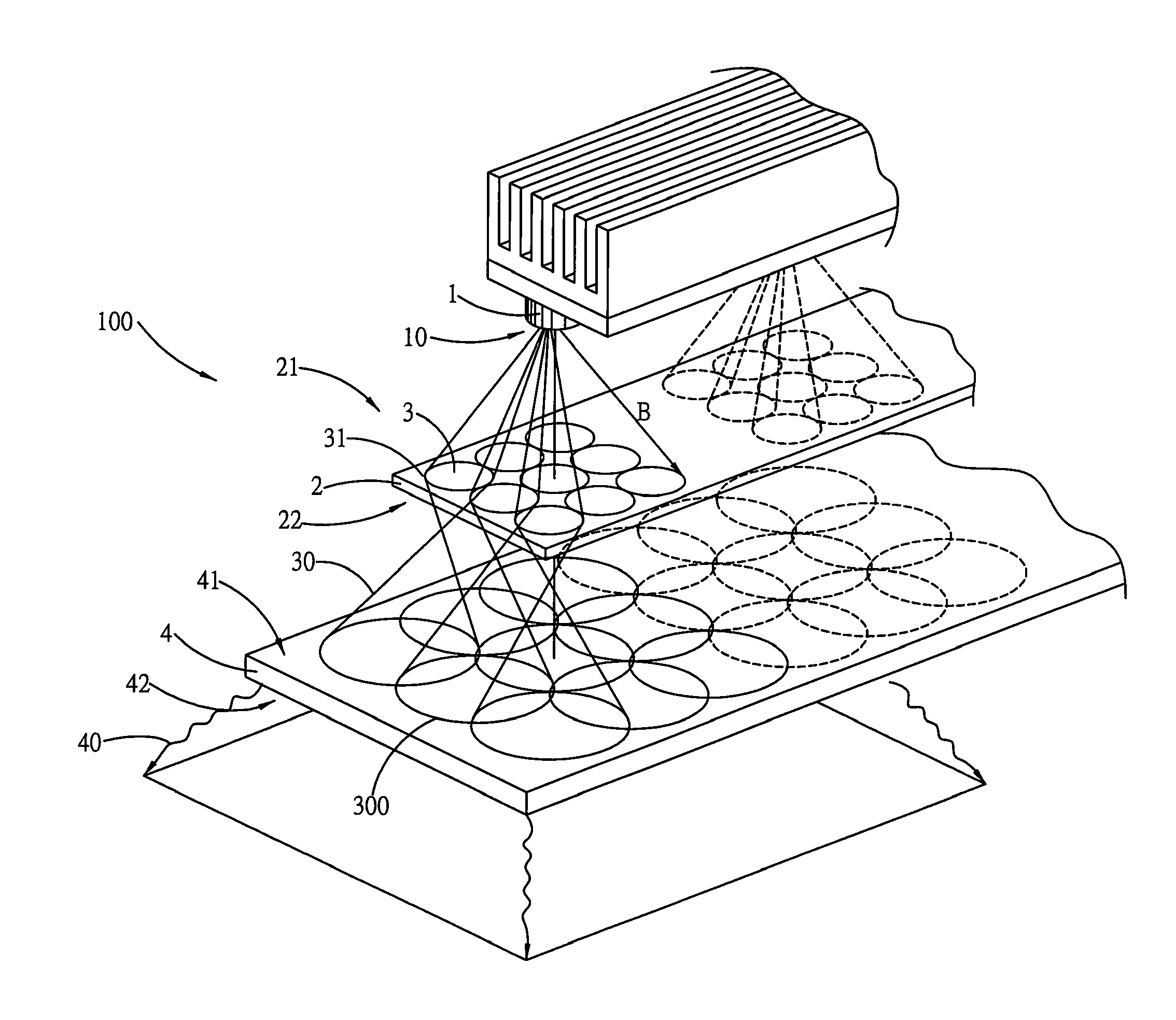
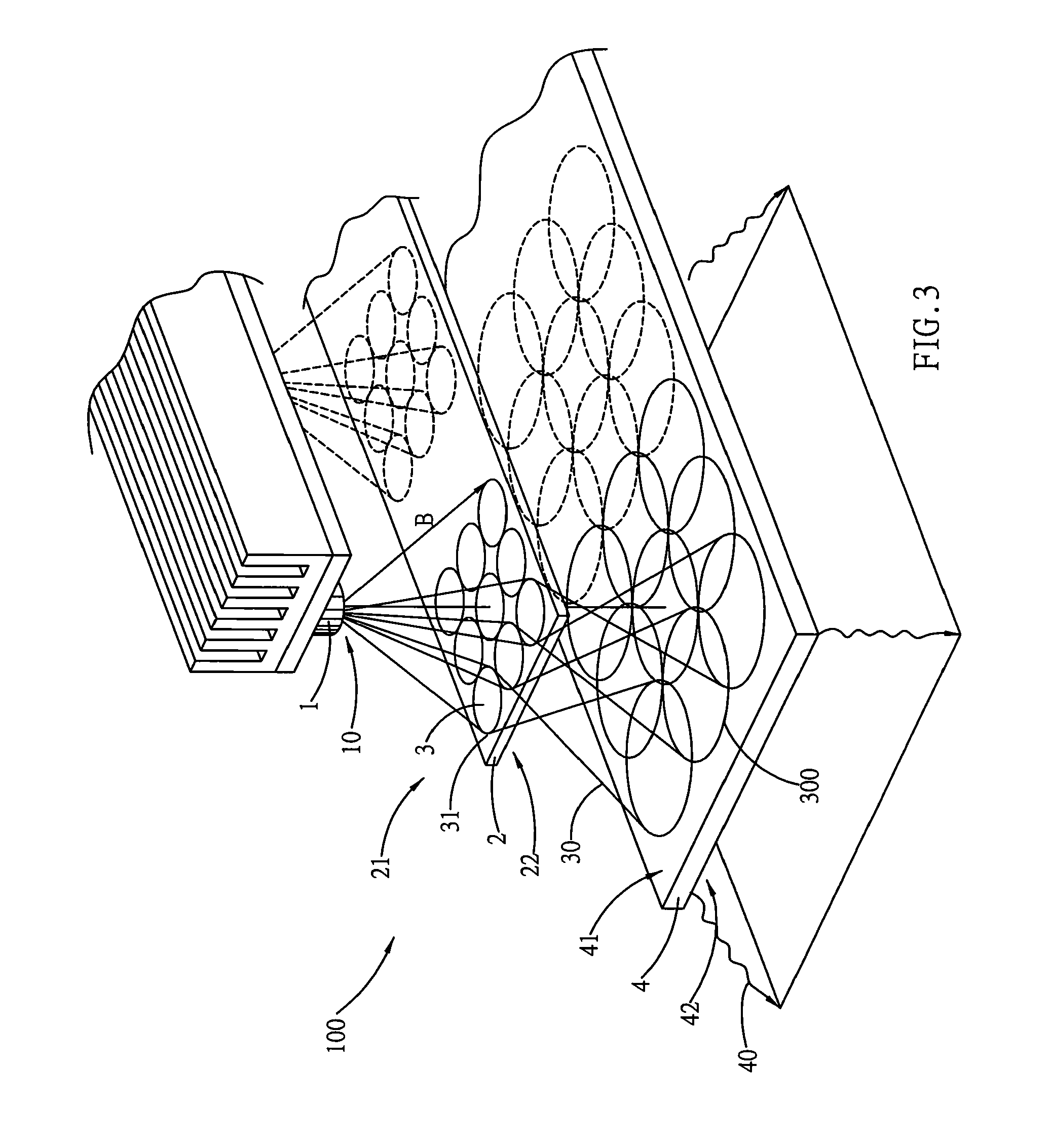
[0023]The present invention relates to a light beam shaping system, which has particular application with light excitation chips, and the like, in which a total quantity of light is split into multiple arrays of conical light beams using pre-dividing means. The actual optical surfaces formed at the bottom portions of the conical light beams simultaneously act on an optical diffusing component, and refraction and diffusion at the optical diffusing component results in illumination brightness of greater uniformity at the light emitting illuminating surface of the system. Let it be known here that the description of the embodiments of the present invention does not take into account oblique incidence at the lens, or spherical aberration.

[0024]Regarding the design, substance and operational principle of the present invention, referring first to FIGS. 3 and 4, which show a shaping system 100 of the present invention, the basic structure of which comprises light-emitting elements 1, a div...


PUM


Abstract

The present invention provides an illumination beam shaping system, which enables the emergent surface of a lighting system of light excitation chips to emit a light beam of uniform illumination brightness. The present invention uses a dividing device, structured from curved lenses arranged in an array, to effect a pre-dividing operation on the total quantity of light from a light excitation chip, after which post-diffusion is carried out to form a light beam with uniform illumination brightness. A plurality of conical light beams in an array are shaped and emerge from an output side, and the bottom portion of each of the conical light beams form an actual optical surface, which act on an optical diffusing component for refraction and diffusion processing, thereby enabling the emergent face of the system to obtain uniform illumination brightness.

Description

BACKGROUND OF THE INVENTION[0001](a) Field of the Invention[0002]The present invention provides an illumination beam shaping system, and more particularly provides an illumination beam shaping system which enables the emergent surface of a lighting system of light excitation chips to emit a light beam of uniform illumination brightness. The present invention produces a light beam from a point light source, such as an electrooptical light source, and a division operation is carried out at a position of the cross section of the light in the forward path of the light beam, whereby blocks of small areas of the projected cross section breadth of the light beam are divided and transformed into a plurality of juxtaposed conical light beams at different angular positions, and the bottom surface of each of the conical light beams distanced from the focal points thereof forms an actual optical surface. The actual optical surfaces act on an incident plane of an optical diffusing component, the...

Claims


Application Information

Patent Timeline
Patent Type & Authority Applications(United States)
IPC IPC(8): F21V13/02
CPCF21V5/007F21V5/008F21Y2101/02G02B19/0061G02B19/0023G02B19/0014G02B27/0961F21Y2115/10
Inventor WEI, CHING-WEI
Owner WEI CHING WEI
Why Eureka
Try Eureka