Piezoelectric acoustic transducer

a technology of piezoelectric loudspeakers and acoustic transducers, which is applied in the direction of electrical transducers, deaf-aid sets, transducer details, etc., can solve the problems of piezoelectric loudspeakers, difficulty in reducing the thickness of loudspeakers, and countermeasures to be taken, so as to increase the voltage sensitivity in the low-frequency band and the effect of greater displacemen

Active Publication Date: 2012-03-08
PANASONIC INTELLECTUAL PROPERTY MANAGEMENT CO LTD
View PDF14 Cites 54 Cited by
  • Summary
  • Abstract
  • Description
  • Claims
  • Application Information

AI Technical Summary

Benefits of technology

[0019]According to the present invention, the piezoelectric diaphragms of the plurality of speaker circuits are alternately displaced in antiphase. Accordingly, greater displacement can be obtained using the voltage used for one speaker circuit, and therefore, the voltage sensitivity in the low-frequency band is increased.

Problems solved by technology

The electrodynamic loudspeakers, however, employ a driving type that requires a magnet and a voice coil, and thus it is difficult to reduce the thickness of the loudspeakers.
Further, the electrodynamic loudspeakers use a magnetic circuit, and thus a problem arises that countermeasures must be taken against magnetic leakage, or the like.
On the other hand, the piezoelectric loudspeakers have a disadvantage that an amount of displacement of a piezoelectric diaphragm is small, as compared to the electrodynamic loudspeakers, when the same voltage is applied.
Because of this, in a low-frequency band where a large displacement is required, a sound pressure becomes small (i.e., voltage sensitivity becomes low), and thereby a problem arises that audio signals cannot be reproduced with a sufficient sound pressure.

Method used


Image

  • Piezoelectric acoustic transducer
  • Piezoelectric acoustic transducer
  • Piezoelectric acoustic transducer

Examples


first embodiment

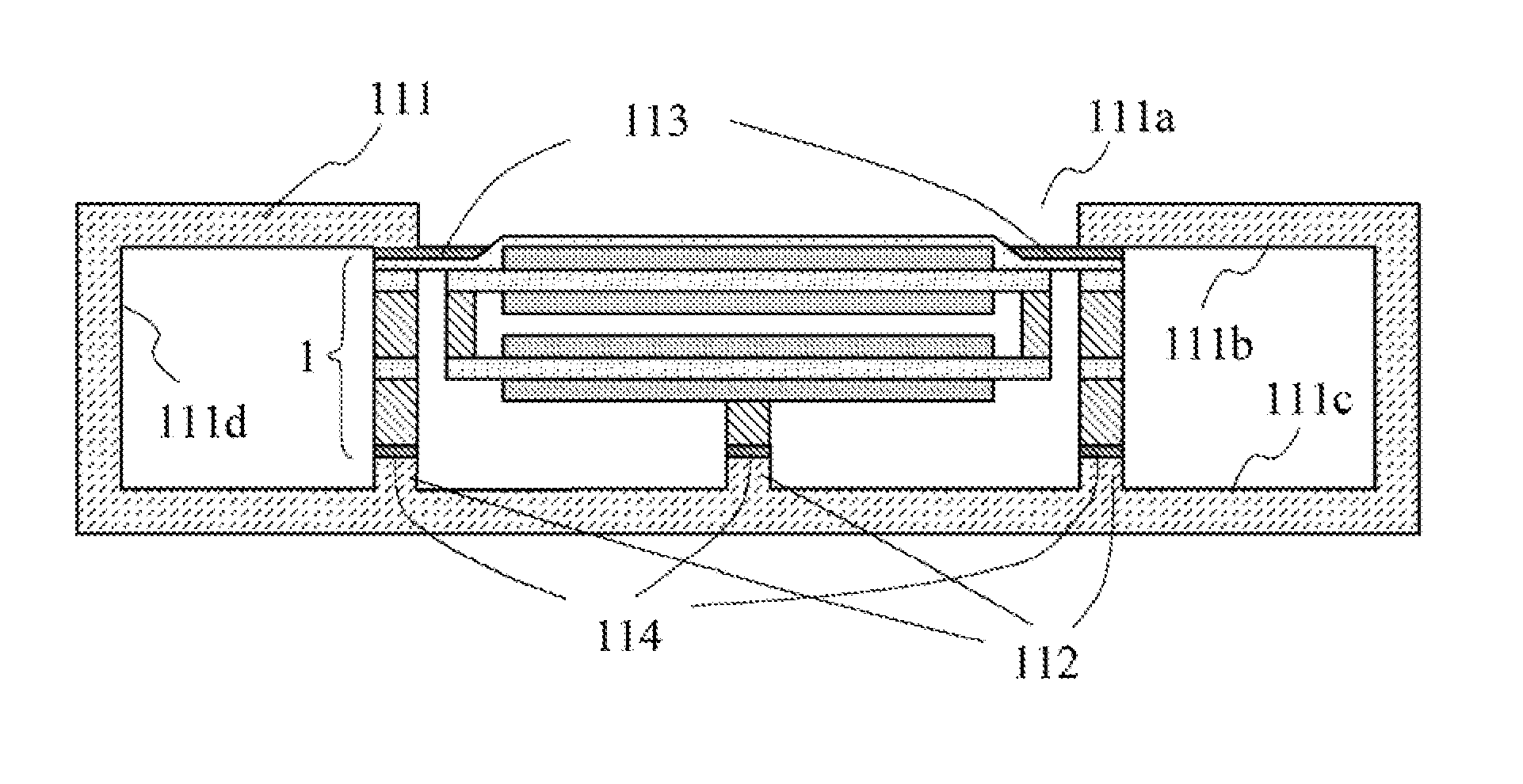
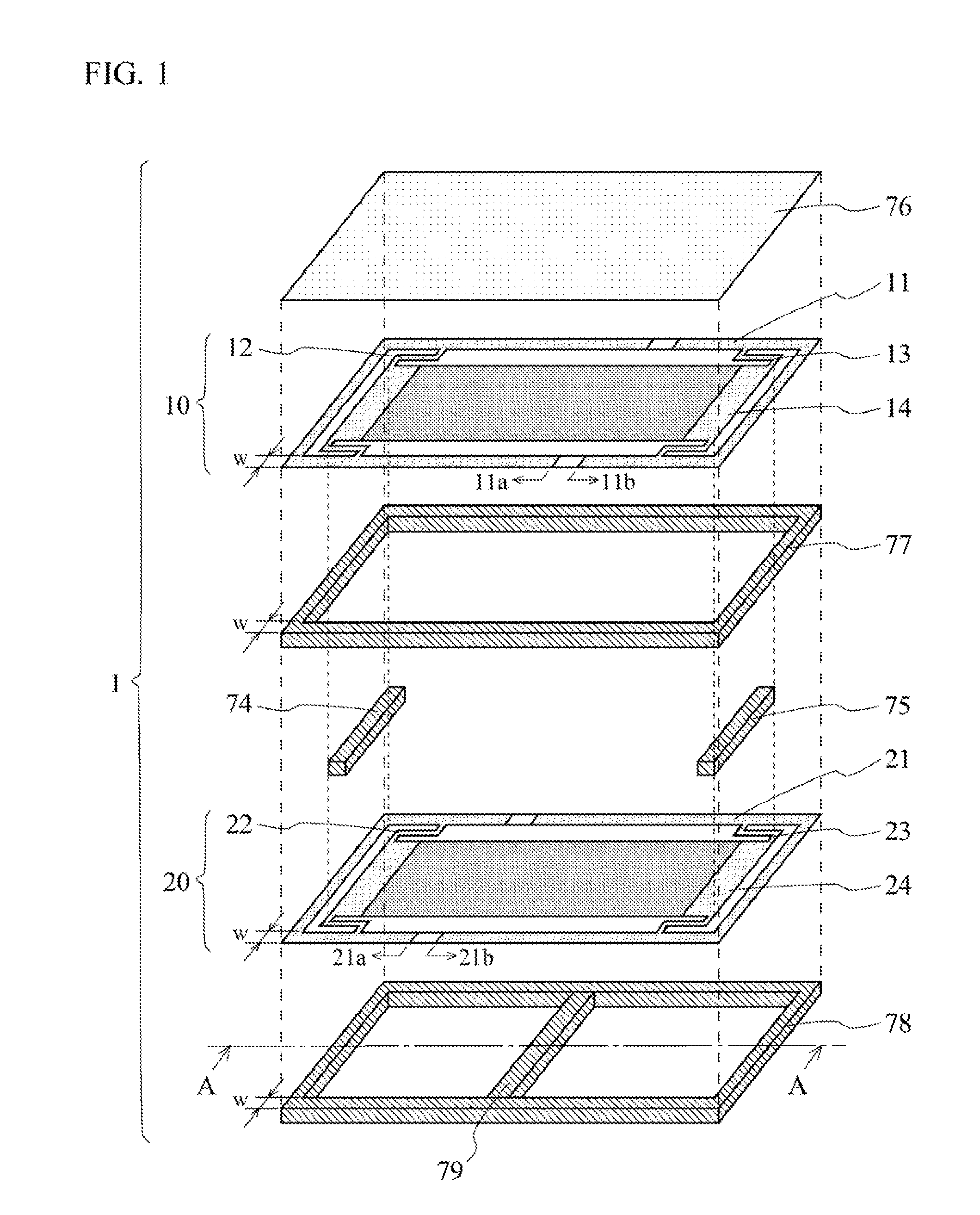
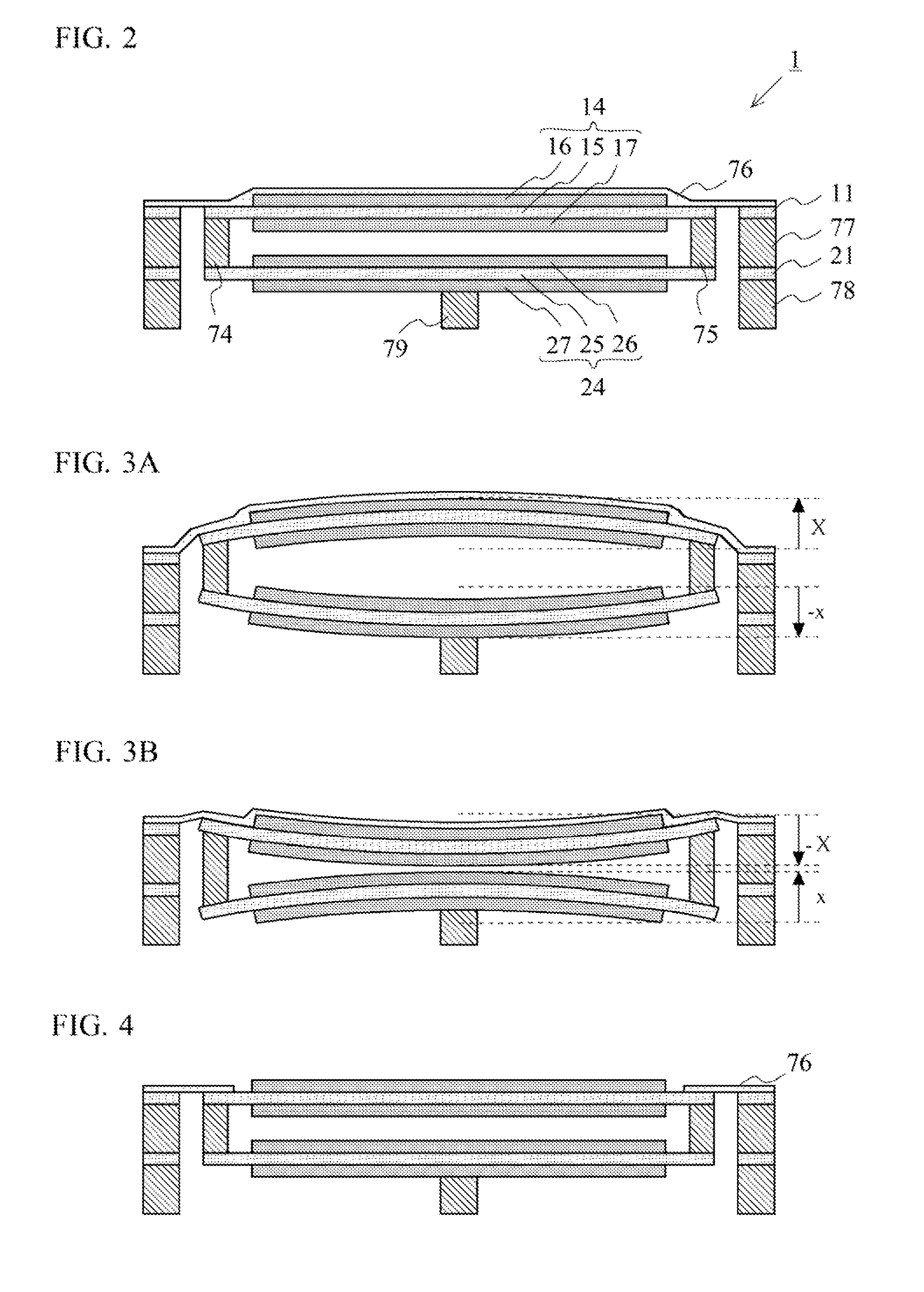
[0040]FIG. 1 is an exploded view showing a structure of a piezoelectric acoustic transducer 1 according to a first embodiment of the present invention. FIG. 2 is a cross-sectional view of the piezoelectric acoustic transducer 1, shown in FIG. 1, taken along a line A-A. FIG. 3A and FIG. 3B are diagrams each illustrating a vibration operation of the piezoelectric acoustic transducer 1 shown in FIG. 1.

[0041]The piezoelectric acoustic transducer 1 according to the first embodiment of the present invention includes an upper speaker circuit 10, a lower speaker circuit 20, coupling members 74 and 75, a surround 76, an upper frame 77, and a lower frame 78. The upper speaker circuit 10, the lower speaker circuit 20, the surround 76, the upper frame 77, and the lower frame 78 are each formed in a polygon with four right angles that has the same size. FIG. 1 illustrates an example in a case where this shape is rectangle having a perimeter R.

[0042]First, description is given of a structure of t...

second embodiment

[0057]FIG. 5 is an exploded view showing a structure of a piezoelectric acoustic transducer 2 according to a second embodiment of the present invention. FIG. 6 is a cross-sectional view of the piezoelectric acoustic transducer 2, shown in FIG. 5, taken along a line B-B.

[0058]The piezoelectric acoustic transducer 2 according to the second embodiment of the present invention includes an upper speaker circuit 30, a lower speaker circuit 20, coupling members 74 and 75, a surround 76, an upper frame 77, and a lower frame 78. This piezoelectric acoustic transducer 2 is different from the piezoelectric acoustic transducer 1 described above in a configuration of the upper speaker circuit 30. Hereinafter, the same reference characters are given to the components that are the same as those of the piezoelectric acoustic transducer 1, and description thereof is omitted. Hereinafter, different configurations are mainly described.

[0059]The upper speaker circuit 30 includes a piezoelectric diaphra...

third embodiment

[0062]FIG. 7 is an exploded view showing a structure of a piezoelectric acoustic transducer 3 according to a third embodiment of the present invention. FIG. 8 is a cross-sectional view of the piezoelectric acoustic transducer 3, shown in FIG. 7, taken along a line C-C. FIGS. 9A and 9B are diagrams each illustrating a vibration operation of the piezoelectric acoustic transducer 3 shown in FIG. 7.

[0063]The piezoelectric acoustic transducer 3 according to the third embodiment of the present invention includes an upper speaker circuit 10, a lower speaker circuit 40, a coupling member 80, a surround 76, an upper frame 77, and a lower frame 81. This piezoelectric acoustic transducer 3 is different from the piezoelectric acoustic transducer 1 described above in terms of configurations of the lower speaker circuit 40, the coupling member 80, and the lower frame 81. Hereinafter, the same reference characters are given to the components that are the same as those of the piezoelectric acoustic...


PUM


Abstract

A piezoelectric acoustic transducer (1) of the present invention includes a lower frame (78), a lower speaker circuit (20), an upper frame (77), an upper speaker circuit (10), and a surround (76). The upper speaker circuit (10) has a piezoelectric diaphragm (14) in which piezoelectric elements (16, 17), each having a structure that flat plate electrodes are disposed on top and bottom of a piezoelectric member, are mounted on top and bottom surfaces of a board (15). The lower speaker circuit (20) has a piezoelectric diaphragm (24) in which piezoelectric elements (26, 27), each having the same structure, are mounted on a top surface and a bottom surface of a board (25). The piezoelectric diaphragms (14, 24) are coupled to each other via coupling members (74, 75). At an application of a voltage, the piezoelectric diaphragms (14, 24) are caused to curve in directions opposite to each other. Having this structure, the piezoelectric acoustic transducer (1) has an increased displacement in a thickness direction thereof, and thereby achieving high quality sound with space-saving.

Description

TECHNICAL FIELD[0001]The present invention relates to a piezoelectric acoustic transducer, and, more particularly, to a piezoelectric loudspeaker that achieves both space-saving and high quality sound.BACKGROUND ART[0002]Recently, there is an accelerating tendency that mobile devices, such as mobile phones, personal digital assistances (PDA), and portable navigation devices, are thinned and downsized. The need for thinner and smaller components to be mounted in audiovisual equipment and the like has also been increasing.[0003]In general, electrodynamic loudspeakers are used as a loudspeaker for reproducing audio signals or music signals in the mobile devices. The electrodynamic loudspeakers, however, employ a driving type that requires a magnet and a voice coil, and thus it is difficult to reduce the thickness of the loudspeakers. Further, the electrodynamic loudspeakers use a magnetic circuit, and thus a problem arises that countermeasures must be taken against magnetic leakage, or...

Claims


Application Information

Patent Timeline
Patent Type & Authority Applications(United States)
IPC IPC(8): H04R17/00
CPCH04R1/288H04R7/20H04R2499/15H04R2499/11H04R17/00H04R7/24H10N30/20
Inventor FUJISE, AKIKOMATSUMURA, TOSHIYUKI
Owner PANASONIC INTELLECTUAL PROPERTY MANAGEMENT CO LTD
Why Eureka
Try Eureka