Object estimation device, method and program

a technology of object estimation and object position, applied in the field of object estimation device, object estimation method and object estimation program, can solve the problems of inability to achieve accurate object detection and difficult to speed up the operation, and achieve the effect of accurate object position estimation, accurate object position and size estimation, and efficient object size estimation

Active Publication Date: 2012-03-08
FUJIFILM CORP
View PDF4 Cites 9 Cited by
  • Summary
  • Abstract
  • Description
  • Claims
  • Application Information

AI Technical Summary

Benefits of technology

[0020]According to the object estimation device, the object estimation method and the object estimation program of the invention, a plurality of smoothed images of different scales are generated by repeating convolution of an image with a smoothing filter having filtering characteristics corresponding to a contour of an object, a plurality of differential images are generated by calculating a difference between each pair of the smoothed images apart from each other by a predetermined scale interval in the generated smoothed images, a combined image is generated by combining the generated differential images, and a position of the object is estimated from a position where a maximum or minimum signal value is found in the generated combined image. In this manner, high-speed and accurate estimation of the position of an object can be achieved.
[0021]In the case where the size estimating means for estimating the size of the object from the differential image with the largest differential value or the smallest differential value among the differential images generated by the differential image generating means is provided, estimation of the size of the object can be achieved without generating multi-resolution images as in the conventional techniques, thereby allowing efficient estimation of the size of the object.
[0022]In the case where the smoothing means generates the a×k pieces of smoothed images L(x, y, σi) (where σi is a scale of the smoothing filter and i=1 to a×k), and the differential image generating means generates the k pieces of differential images G(x, y, σi) (k is an integer of 2 or more) according to equation (1) above with using the a×k pieces of smoothed images L(x, y, σi), accurate estimation of the position and size of the object can be achieved.
[0023]In the case where the preprocessing means for generating a resolution-reduced image from the inputted original image is provided, faster detection can be achieved with the resolution of the image reduced to some extent without impairing the accuracy of detection.
[0024]In the case where the object detecting means for detecting the object in the image based on the position of the object estimated by the position estimating means is provided, more accurate and efficient detection of the object can be achieved with focusing the detection of the object in an area around the position estimated by the position estimating means.

Problems solved by technology

However, the techniques disclosed in Patent Documents 1 and 2 require generation of the differential image between each pair of smoothed images of adjacent scales, and it is necessary to generate a large number of differential images for a large number of resolution images.
Therefore, speeding up of the operation is difficult to be achieved.
Further, in the case where only the Gaussian filter based on the contour is applied, as disclosed in Patent Document 3, it is impossible to achieve accurate object detection.

Method used


Image

  • Object estimation device, method and program
  • Object estimation device, method and program
  • Object estimation device, method and program

Examples


Embodiment Construction

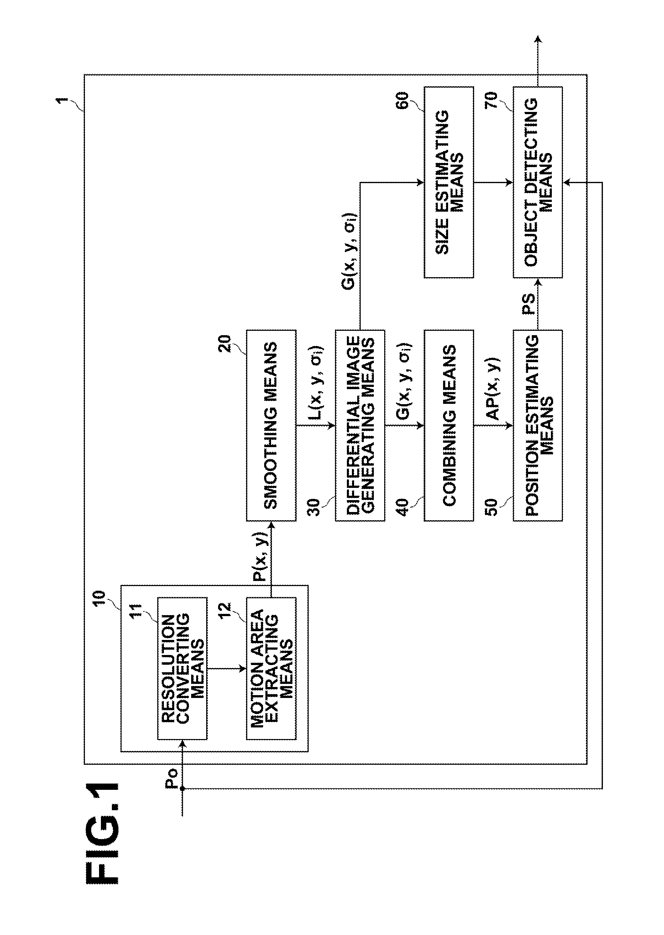
[0034]Hereinafter, embodiments of the present invention will be described in detail with reference to the drawings. FIG. 1 is a block diagram illustrating a preferred embodiment of an object estimation device of the invention. It should be noted that the configuration of an object estimation device 1, as shown in FIG. 1, is implemented by running an object estimation program, which is read in an auxiliary storage device of a computer (such as a personal computer), on the computer. The object estimation program may be stored in an information storage medium, such as a CD-ROM, or distributed over a network, such as the Internet, to be installed on the computer.

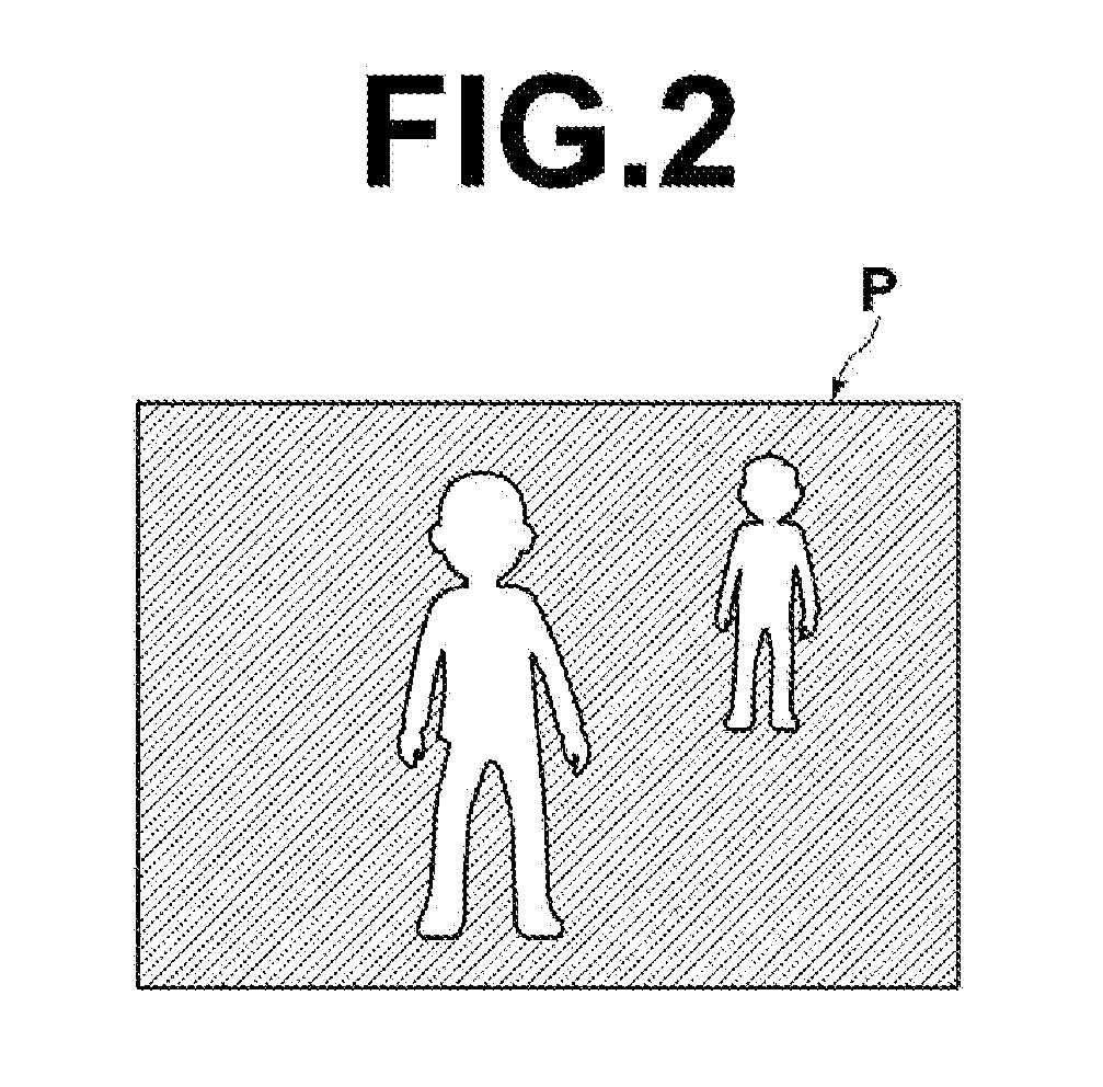
[0035]The object estimation device 1 shown in FIG. 1 detects, for example, a person's head in a moving image as the object. The object estimation device 1 includes a preprocessing means 10, a smoothing means 20, a differential image generating means 30, a combining means 40, a position estimating means 50, a size estimating mean...


PUM


Abstract

Efficient and accurate estimation of the position and size of an object is achieved. Convolution of an image with a smoothing filter is repeated to generate a plurality of smoothed images L(x, y, σi) of different scales. Then, a differential image G(x, y, σi) between each pair of the smoothed images L(x, y, σi) of scales σi and σi×2 is generated. Then, a combined image AP is generated by combining the differential images G(x, y, σi), and a position estimating unit estimates the position of the object based on the combined image AP.

Description

BACKGROUND OF THE INVENTION[0001]1. Field of the Invention[0002]The present invention relates to an object estimation device, an object estimation method and an object estimation program for estimating position and size of an object in an image.[0003]2. Description of the Related Art[0004]As a method for detecting a specific object, such as a face or a person in an image, detection methods using an image pyramid have been proposed (see, for example, U.S. Patent Application Publication Nos. 2009324087 and 2008247651, which are hereinafter referred to as Patent Documents 1 and 2). In the techniques disclosed in Patent Documents 1 and 2, a plurality of smoothed images of different scales are generated by repeating convolution of an image with a Gaussian filter. Then, a differential image between each pair of the smoothed images of adjacent scales is generated (which is also referred to as a DOG (difference of Gaussian) image). The generation of the DOG images is carried out for each of...

Claims


Application Information

Patent Timeline
Patent Type & Authority Applications(United States)
IPC IPC(8): G06K9/40G06K9/00
CPCG06T7/0042G06T2207/20221G06T2207/20016G06T7/73
Inventor YONAHA, MAKOTO
Owner FUJIFILM CORP
Why Eureka
Try Eureka