Connector assembly with improved cooling capability

a technology of cooling capability and connector assembly, which is applied in the direction of coupling device details, coupling device connection, coupling device two-part connection, etc., can solve the problems of increasing the amount of heat that the connector has to dissipate, poor airflow over the module, and increasing the energy passing through the connector, so as to facilitate air flow and improve the cooling capability

Active Publication Date: 2012-03-08
MOLEX INC
View PDF3 Cites 89 Cited by
  • Summary
  • Abstract
  • Description
  • Claims
  • Application Information

AI Technical Summary

Benefits of technology

[0006]In an embodiment, a cage with improved cooling capability is provided for a stacked connector. The cage is formed from a plurality of walls including a top wall, a bottom wall, two side walls and a rear wall. These walls cooperatively define a hollow enclosure with an interior space that envelops a housing. The hollow enclosure is divided into at least an upper and lower bay and includes a central portion positioned between the upper and lower bay and defined, at least in part by a spacer. In operation, a pluggable module can be inserted into the bays so that an edge-card can be inserted into the corresponding slot(s) and contact pads on the edge card can engage terminals supported by the housing. The central portion includes a front face with apertures so that air can be drawn into the center portion through the front face. The side walls include apertures aligned with the center portion so that air can be drawn out of the center portion. In this manner, when the cage is positioned in an enclosure that has a negative internal pressure, air will flow through the apertures in the front face and out the apertures in the side wall so as to provide cooling. In an embodiment, the cage may be a ganged cage with two or more sets of upper and lower bays positioned side by side and separated by a dividing wall. The dividing wall may also have apertures aligned with the center portion so as to facilitate air flow into and out of the center portion in a desired manner.

Problems solved by technology

However, with the increase in shielding comes a resultant poor airflow over the module.
This lack of air-flow can create problems because at higher data rates the amount of energy passing through the connector increases and the increased energy increases the amount of heat that the connector has to dissipate.
While the use of a heat sink has helped address this heat dissipation issue, one configuration that has been difficult to address is a stacked connector configuration is used.
While air can be directed over the top of a stacked connector (the top of which can readily include a heat sink with fins to help dissipate heat), the lower connector is effectively sandwiched between an insulating circuit board and a heat generating module, making cooling particularly challenging.
As can be appreciated, however, this creates problems in plugging in modules because some modules will need to be turned upside down and it can be difficult to tell which way to turn the module when a person is facing a number of rows of such connectors.
Furthermore, the split orientation of the connectors limits the interface with the circuit board that supports the connectors.

Method used


Image

  • Connector assembly with improved cooling capability
  • Connector assembly with improved cooling capability
  • Connector assembly with improved cooling capability

Examples


Embodiment Construction

[0028]The detailed description that follows describes exemplary embodiments and is not intended to be limited to the expressly disclosed combination(s). Therefore, unless otherwise noted, features disclosed herein may be combined together to form additional combinations that were not otherwise shown for purposes of brevity.

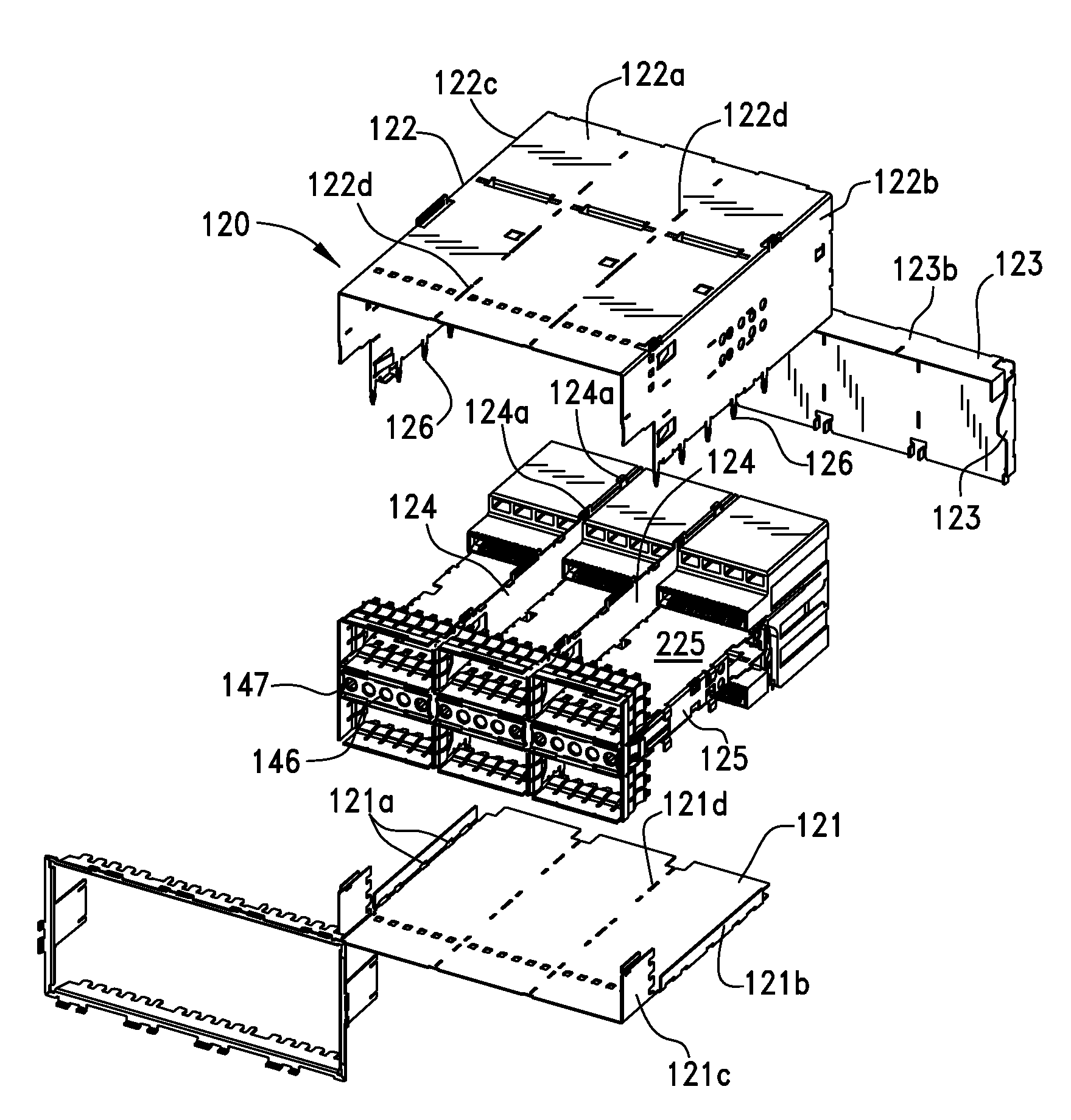
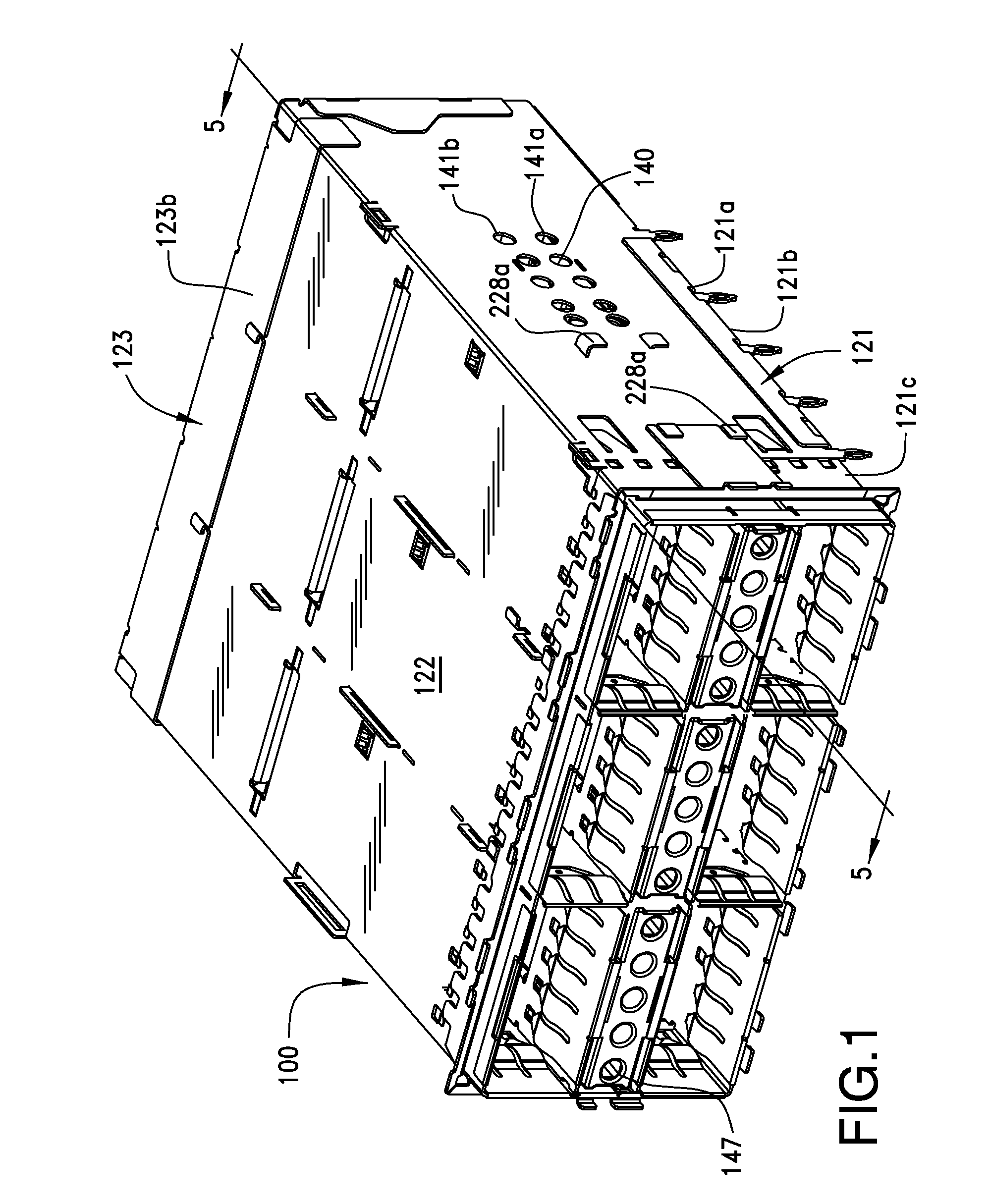
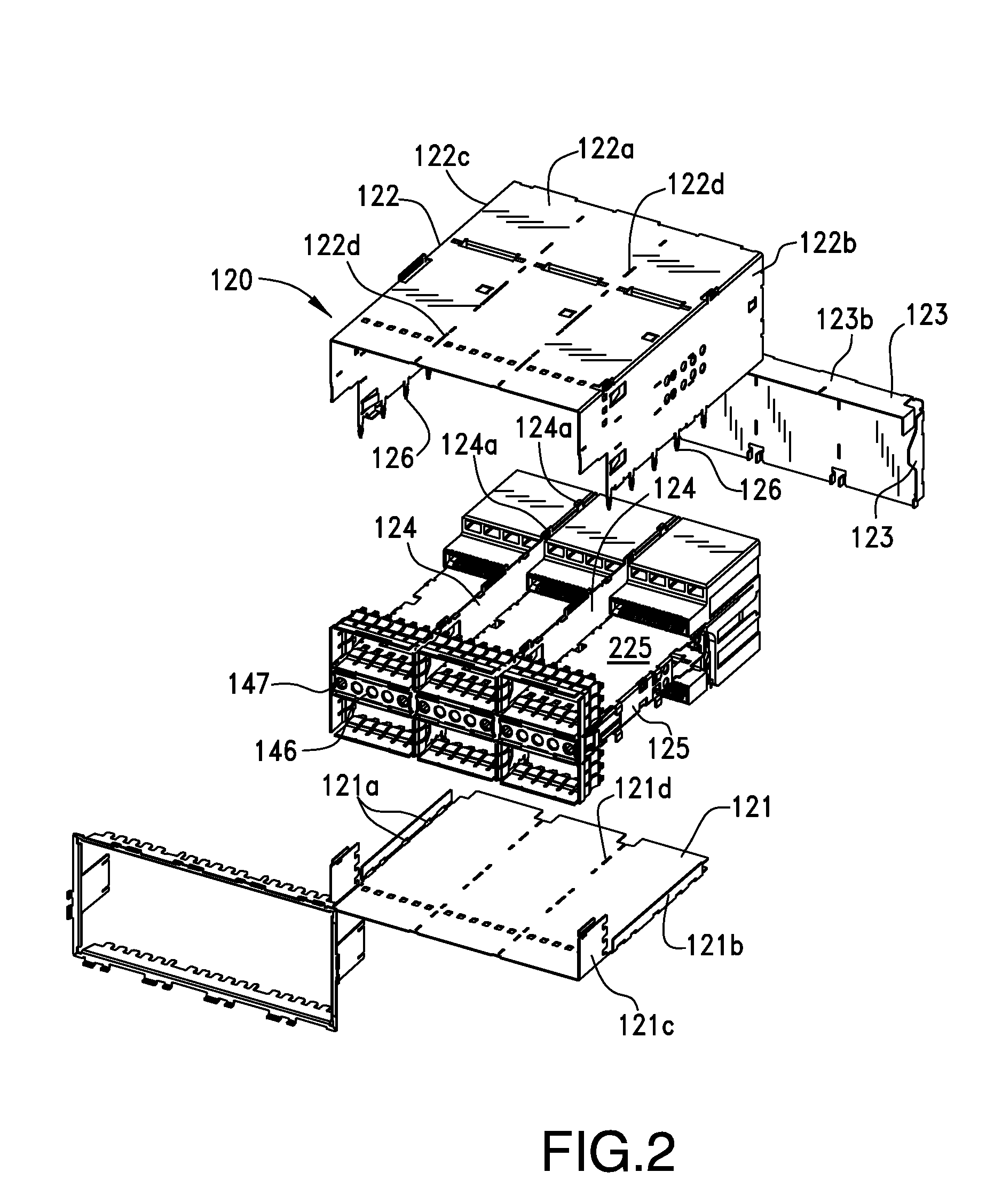
[0029]Before looking at the figures, it should be noted that a number of different methods of assembling walls together to form the cage assembly. In general, a stacked cage assembly may include a first wall and a second wall that are used to form sides of the cage assembly. The cage assembly may further include a third wall that extends between the first and second wall to form a top of the cage assembly. A fourth wall may extend between the first and second wall to form a back wall. A fifth and sixth wall may be positioned so as to extend between the first and second wall in an orientation that is substantially parallel to each near the middle of the first and s...


PUM


Abstract

A connector includes a cage that has two side walls, a top cover and a rear wall that are combined to form a hollow enclosure. The enclosure is separated into two module-receiving bays by at least one spacer with a top and bottom wall that extends between the sidewalls to form a central portion between a top and bottom bay, the central portion acting as an air passage between a front face and the sides of the connectors. Air openings are formed in the sidewalls of the cage assembly and they communicate with the central portion. The bottom wall of the spacer is provided with a large opening that extends a substantial distance of module-receiving bay and provides an air flow path from the air openings to the bottom module-receiving bay. An insert with apertures in communication with the central portion can be positioned

Description

REFERENCE TO RELATED APPLICATIONS [0001]This application is a national phase of PCT Application No. PCT / US2010 / 026650, filed Mar. 10, 2010, which in turn claims priority to U.S. Provisional Application No. 61 / 159,029, filed Mar. 10, 2009, both of which are incorporated herein by referenced in their entirety.BACKGROUND OF THE INVENTION [0002]The present invention relates generally to high speed pluggable connectors, and more particularly, to shielded, pluggable connectors with improved cooling capabilities.[0003]Moore's Law, which is more properly termed an observation, is based on the understanding that in the field of integrated circuits, the complexity (or number of circuits) will double every two years. The fact that this observation has held true since about 1965 has had a remarkable impact on the world as we know it. Computation speeds that were in the realm of science fiction have become a reality. Moore's Law, as it is known, continues and while there appear to be fundamental...

Claims


Application Information

Patent Timeline
Patent Type & Authority Applications(United States)
IPC IPC(8): H01R13/658H01R13/648H05K9/00
CPCH01R13/65802H01R13/6596H01R13/6586H01R23/6873H01R13/6584H01R13/658H01R12/00
Inventor REGNIER, KENT E.LANG, HAROLD KEITH
Owner MOLEX INC
Why Eureka
Try Eureka