Hinge

Active Publication Date: 2012-03-15
LEOHAB ENTERPRISE
View PDF13 Cites 1 Cited by
  • Summary
  • Abstract
  • Description
  • Claims
  • Application Information

AI Technical Summary

Benefits of technology

[0008]According to the present invention, a hinge is useable in an electronic device which includes a base and a cover, with the cover pivotal with respect to the base through the hinge. The hinge includes a fixing frame, a rotating frame, a support, and a connecting member. The rotating frame is pivotally joined to the fixing frame and includes a joint rotated concurrently with the rotating frame relative to the fixing frame. The support includes a first connecting portion for joining to the base and a second connecting portion. The connecting member is mounted between the rotating frame and the support and includes a first distal end joined to the joint, and a second distal end joined to the second connecting portion. Furthermore, the connecting member is operably moved between an extended position and a retracted position in response to two opposite pivoting directions of the rotating frame with respect to the fixing frame, and in addition, the support moves away from the rotating frame in response to the connection member moving from the retracted position to the extended position thereof. In this regard, the electronic device that employs the hinge is adapted to be gradually elevated from the support by the connecting member as the rotating frame is pivoted away from the fixing frame, and the base and a surface that bears the electronic device by supporting the support including a gradually increased gap therebetween as the cover is pivoted away from the base, which enables air to flow under the base through the gap in order to make the electronic device experience a heat-dissipating effect.
[0009]It is an object of the present invention to provide a hinge that is usable in an electronic device and can make the electronic device experience a heat-dissipating effect.
[0010]It is another object of the present invention to provide a hinge that eliminates the need for remolding the electronic device for the installation of the hinge.
[0011]It is a further object of the present invention to provide a hinge that has a simple structure and the making thereof is cost-saving.

Problems solved by technology

Electronic devices that are made portable, for example, a laptop, generally suffer a problem that internal processors and components thereof crash easily due to that they are fitted in a compact size and their temperatures raise relatively high quickly after a long use period.
Therefore, heat dissipation for these components is always an issue to be dealt with such electronic devices.
However, an additional effort is needed to bring the cooling pad.
Unfortunately, a new mold for the base is needed for making the base adapted to allow the leg to be mounted thereon, therefore, it entails substantially high manufacture cost.
Furthermore, the leg is not adapted to be adjustably fixed at various elevated angles to meet the user's demand, and in addition, the user would experience an abrupt pause or jump during the operation thereof.

Method used


Image

  • Hinge
  • Hinge
  • Hinge

Examples


Embodiment Construction

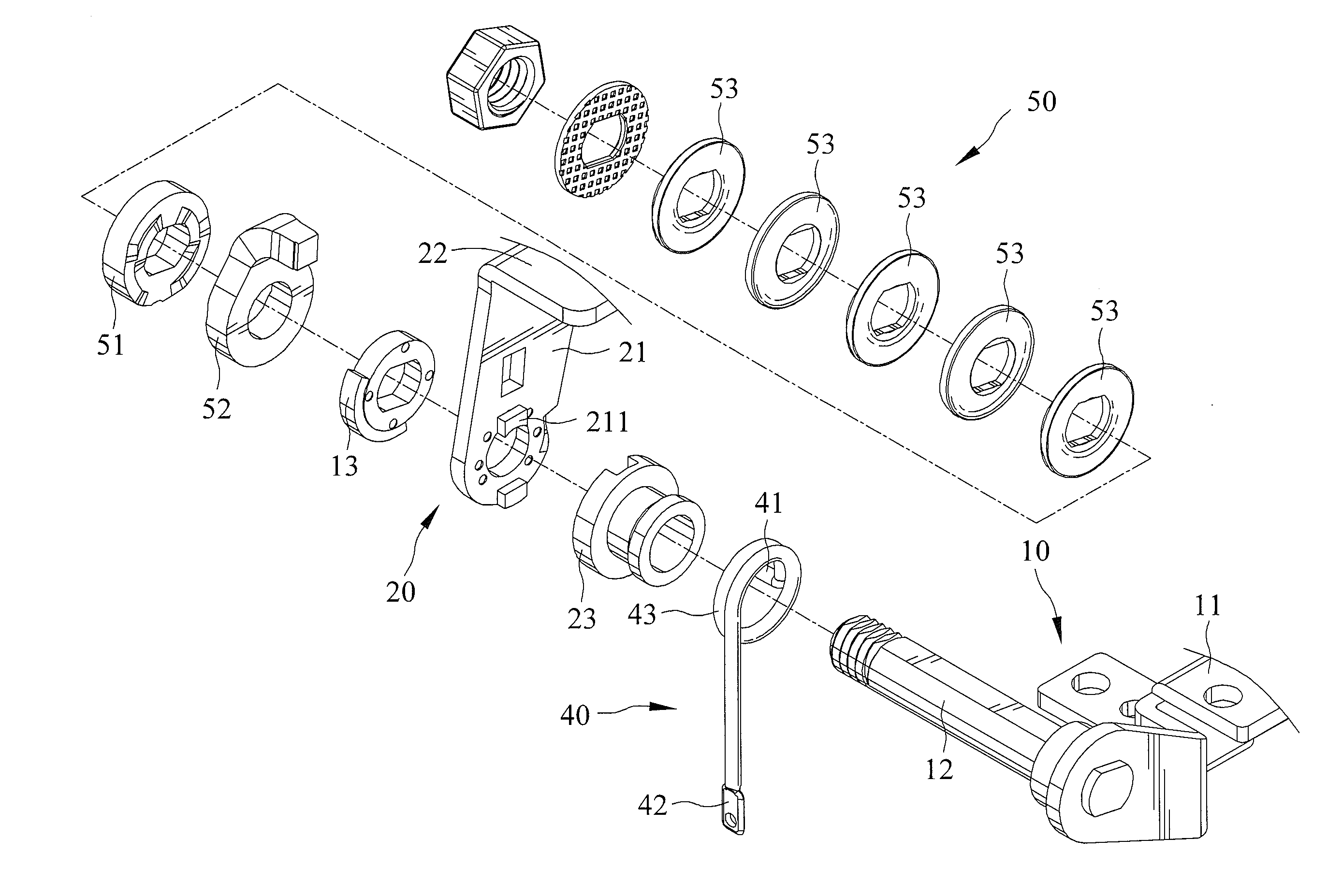
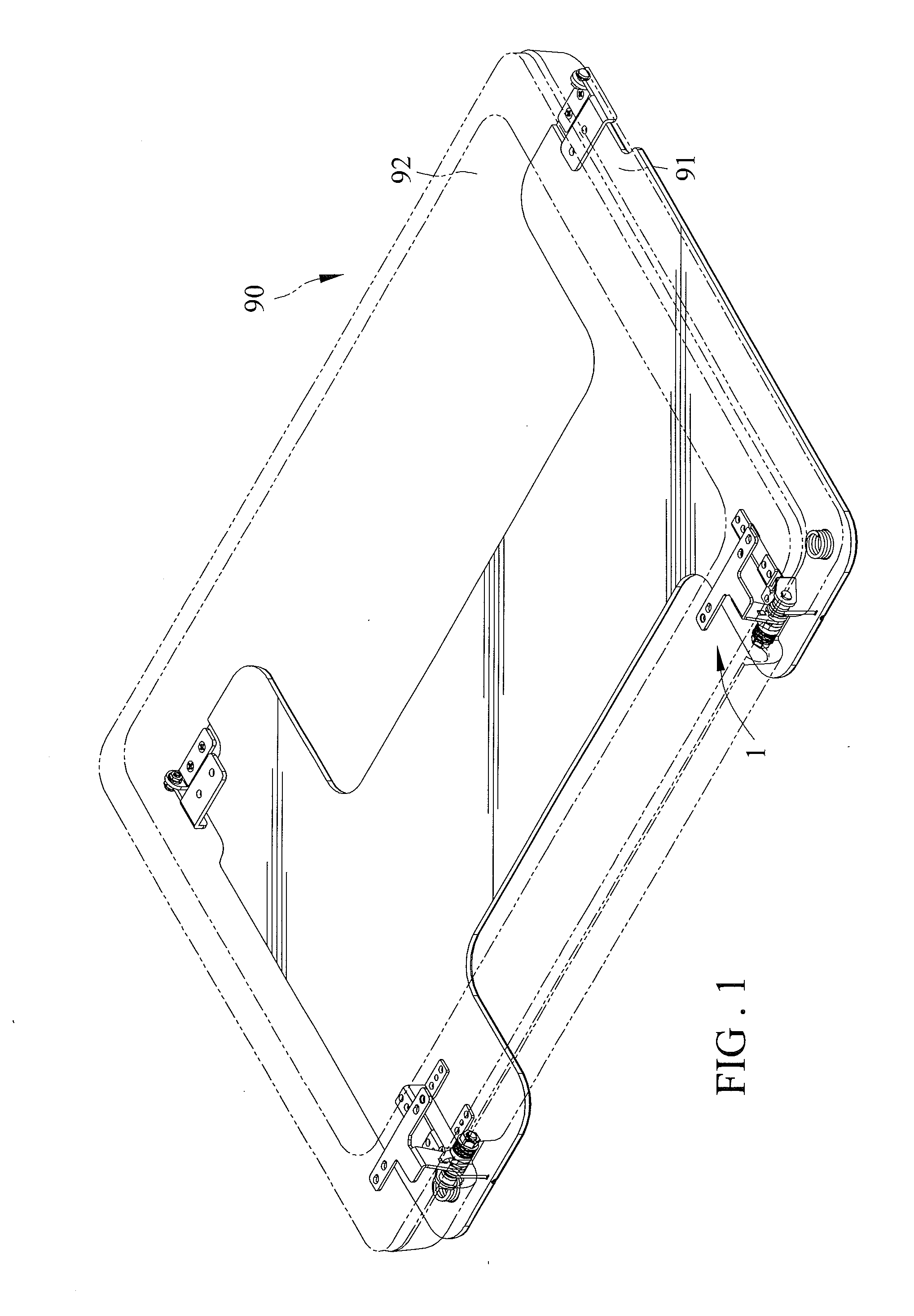
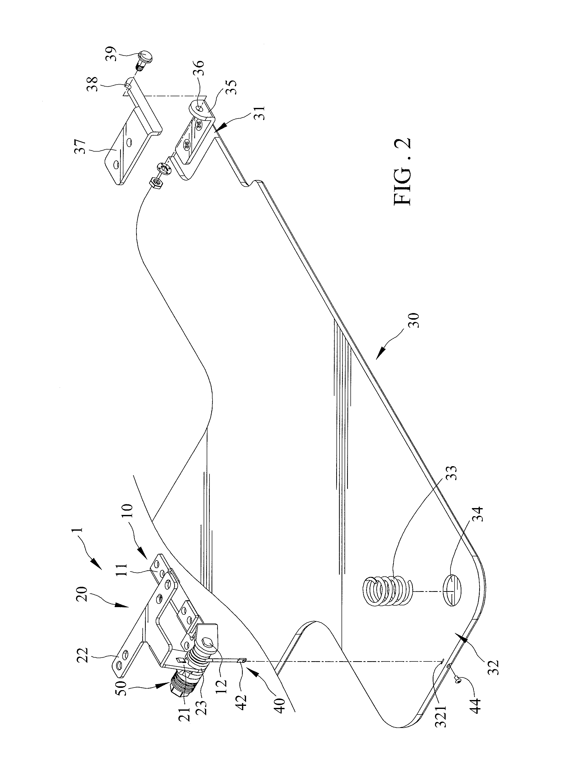
[0022]A hinge 1 in accordance with the present invention includes a fixing frame 10, a rotating frame 20, a support 30, a connecting member 40, and a torque assembly 50. The hinge 1 is usable in an electronic device 90 which has a base 91 and a cover 92.

[0023]The fixing frame 10 includes a fixing end 11, and an axle 12 extending from and non-movably positioned with respect to the fixing end 11. In the electronic device employing the hinge 1, the fixing frame 10 is preferably mounted on the base 91 with the fixing end 11 attaching with the base 91.

[0024]The rotating frame 20 includes an engaging end 21 and is joined to the fixing frame 10 with the engaging end 21 joined to the axle 12 of the fixing frame 10. Furthermore, the rotating frame 20 is rotatable with respect to the fixing frame 10 in a manner that it is pivotal with respect to the fixing frame 10 about the axle 12. The rotating frame 20 also includes a joining end 22 defined at an end of the engaging end 21. In the electron...


PUM


Abstract

A hinge includes a fixing frame, a rotating frame, a support, and a connecting member. The rotating frame is pivotally joined to the fixing frame. The support includes a first connecting portion for joining to the base and a second connecting portion. The connecting member is mounted between the rotating frame and the support. Furthermore, the connecting member is operably moved between an extended position and a retracted position in response to two opposite pivoting directions of the rotating frame with respect to the fixing frame, and in addition, the support moves away from the rotating frame in response to the connection member moving from the retracted position to the extended position thereof.

Description

BACKGROUND OF THE INVENTION[0001]1. Field of the Invention[0002]The present invention relates to a hinge that is usable in an electronic device, and particularly, to a hinge including a connecting member that occupies substantially small internal space of the hinge and is adapted to be operably moved in response to the operation of the hinge to elevate the electronic device from a surface the electronic device is placed to make the electronic device to experience a heat-dissipating effect.[0003]2. Description of the Related Art[0004]Electronic devices that are made portable, for example, a laptop, generally suffer a problem that internal processors and components thereof crash easily due to that they are fitted in a compact size and their temperatures raise relatively high quickly after a long use period. Therefore, heat dissipation for these components is always an issue to be dealt with such electronic devices.[0005]A cooling pad is what is now commonly seen in the market as a sol...

Claims


Application Information

Patent Timeline
IPC IPC(8): E05F1/12E05D7/00
CPCE05D11/087G06F1/1616G06F1/1681E05Y2900/606Y10T16/554Y10T16/5387Y10T16/5472Y10T16/5543Y10T16/5323Y10T16/540345Y10T16/538E05Y2999/00
Inventor LIN, CHAO-CHI
Owner LEOHAB ENTERPRISE
Why Eureka
Try Eureka