
Hybrid heat exchanger apparatus and method of operating the same

a heat exchanger and hybrid technology, applied in heat exchange apparatus, lighting and heating apparatus, triple coolers, etc., can solve the problems of undesirable heat exchangers that emit visible plumes of water condensate, water is considered scarce and valuable resources, and cooling towers can emit plumes. to achieve the effect of inhibiting the formation

Active Publication Date: 2012-03-15
EVAPCO
View PDF2 Cites 15 Cited by
  • Summary
  • Abstract
  • Description
  • Claims
  • Application Information

AI Technical Summary

Benefits of technology

[0014]It is an object of the invention to provide a hybrid heat exchanger apparatus that might inhibit the formation of a plume of water condensate when ambient conditions are optimal for formation of the same.
[0015]It is another object of the invention to provide a hybrid heat exchanger apparatus that conserves water by enhanced dry cooling capabilities.

Problems solved by technology

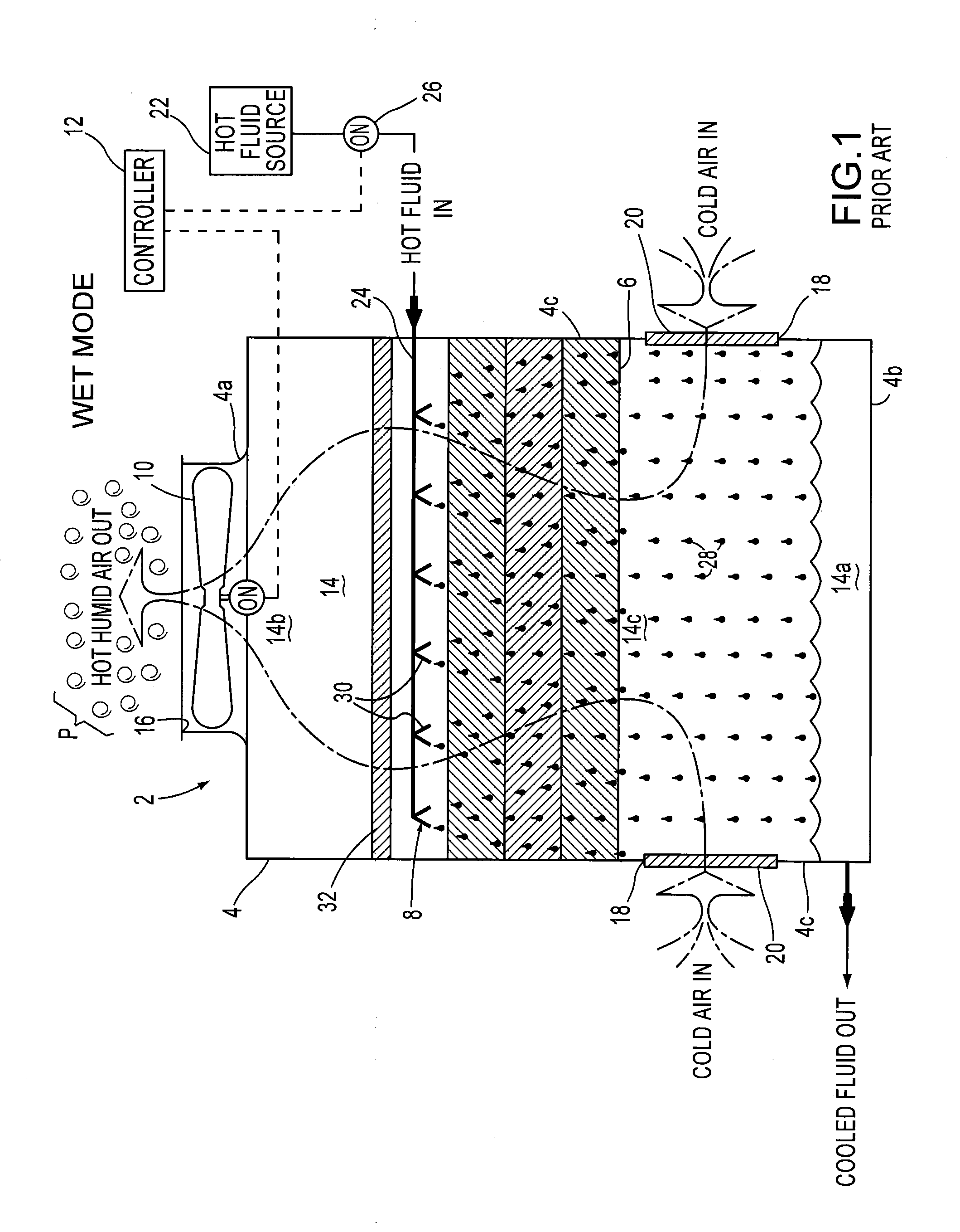
As a result, a heat exchanger that spews a visible plume P of water condensate is undesirable.
First, particularly in cold climates, cooling towers can emit plume when the warm, humid air being discharged from the unit meets the cold, dry air in the ambient environment.
Second, water is considered to be a scarce and valuable resource in certain regions.

Method used


Image

  • Hybrid heat exchanger apparatus and method of operating the same
  • Hybrid heat exchanger apparatus and method of operating the same
  • Hybrid heat exchanger apparatus and method of operating the same

Examples


fifth embodiment

[0062]Since the HOT HUMID AIR and the HOT DRY AIR are isolated from one another, it is possible that a plume P might form above the first fan assembly 10a under the appropriate atmospheric conditions. In brief, although the hybrid heat exchanger apparatus 500 might not abate plume P, it does conserve water.

[0063]In order to execute the method of the ninth embodiment of hybrid heat exchanger apparatus 500 the present invention, the steps of distributing evaporative cooling water on the heat exchanger device and causing ambient air to flow across the heat exchanger device are identical to the method to execute the method of the first through fourth embodiments of the hybrid heat exchanger device described above. In addition thereto, to execute the method of the fifth embodiment of the hybrid heat exchanger device 500, the HOT HUMID AIR and the HOT DRY AIR are isolated from one another inside the hybrid heat exchanger apparatus and thereafter the HOT HUMID AIR and HOT DRY AIR are then ...

seventh embodiment

[0068]A seventh exemplary embodiment of a hybrid heat exchanger apparatus 700 of the present invention in the HYBRID WET / DRY mode is illustrated in FIG. 13. The seventh exemplary embodiment of the hybrid heat exchanger apparatus 700 is similar to the first exemplary embodiment of the hybrid heat exchanger apparatus 100 discussed above and illustrated in FIG. 3. Unlike the first exemplary embodiment of the hybrid heat exchanger apparatus 10, the hybrid heat exchanger apparatus 700 includes a restricted bypass 52. The restricted bypass 52 interconnects the hot fluid source 22 (shown in FIGS. 2 and 3) and the first fluid distribution manifold section 24a while bypassing the second fluid distribution manifold section 24b. Although the hot fluid to be cooled flows through the indirect heat exchanger device 106b, the restricted bypass 52 is operative to restrict the hot fluid to be cooled to flow though the indirect heat exchanger device 106b. The valve 40d can be partially closed so that...


PUM


Abstract

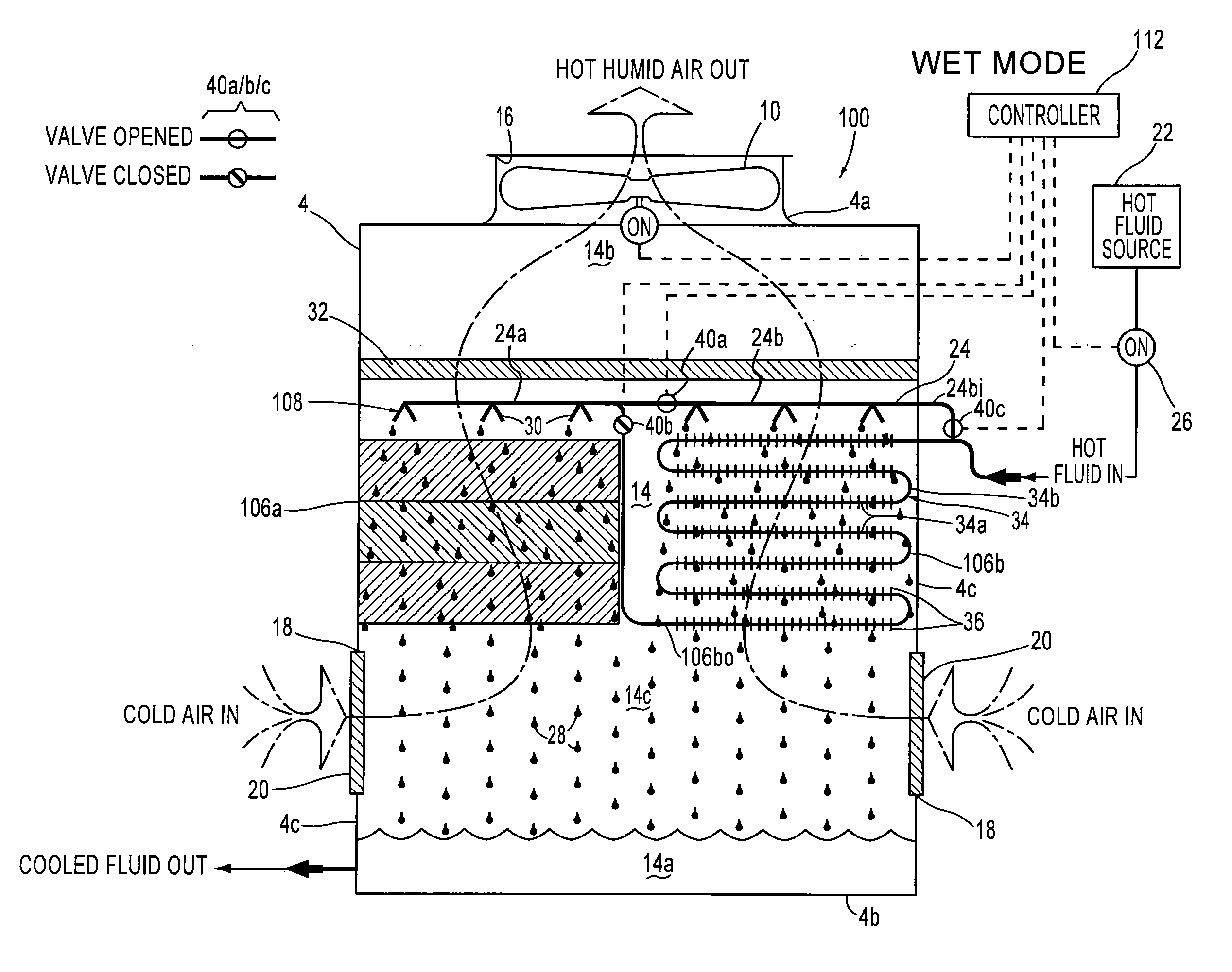
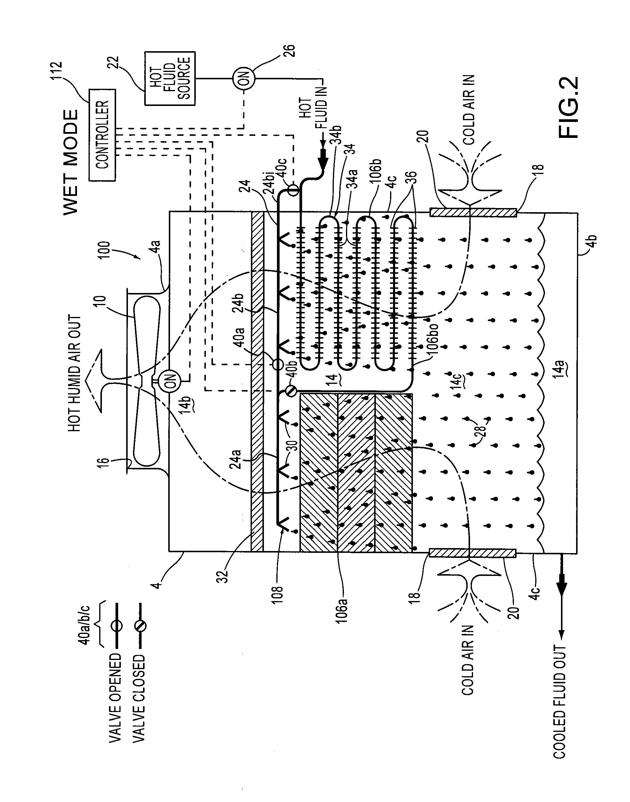
A hybrid heat exchanger apparatus includes a direct heat exchanger device and an indirect heat exchanger device and a method of operating the same encompasses conveying a hot fluid to be cooled from a hot fluid source through the indirect heat exchanger device to a cooling fluid distribution system. The hot fluid to be cooled is distributed from the cooling fluid distribution system onto the direct heat exchanger device. In a hybrid wet / dry mode, ambient air flows across both the indirect heat exchanger device and the direct heat exchanger device to generate hot humid air from the ambient air flowing across the direct heat exchanger device and hot dry air from the ambient air flowing across the indirect heat exchanger device.

Description

CROSS-REFERENCE TO RELATED APPLICATION[0001]This is a Continuation application of application Ser. No. 12 / 882,614, filed on Sep. 15, 2010, the entirety of which is incorporated herein by reference for all purposes.FIELD OF THE INVENTION[0002]The present invention relates to a hybrid heat exchanger apparatus. More particularly, the present invention is directed to a hybrid heat exchanger apparatus that operates in a wet mode and a hybrid wet / dry mode in order to conserve water and, possibly, abate plume.BACKGROUND OF THE INVENTION[0003]Heat exchangers are well known in the art. By way of example, a conventional heat exchanger 2 is diagrammatically illustrated in FIG. 1 and is sometimes referred to as a “cooling tower”. The heat exchanger 2 includes a container 4, a direct heat exchanger device 6, a conventional cooling fluid distribution system 8, an air flow mechanism such as a fan assembly 10 and a controller 12. The container 4 has a top wall 4a, a bottom wall 4b and a plurality o...

Claims


Application Information

Patent Timeline
Patent Type & Authority Applications(United States)
IPC IPC(8): F28D15/00
CPCF28C1/14F28C2001/145F28F27/003F28F25/06
Inventor BUGLER, III, THOMAS W.VADDER, DAVEY J.
Owner EVAPCO
Learn More