
Method of manufacturing a spark plug

a manufacturing method and spark plug technology, applied in the field of spark plugs, to achieve the effects of reducing misfire, improving gas mileage, peak engine performance, and horsepower

Inactive Publication Date: 2012-03-15
HKA INVESTMENTS
View PDF8 Cites 7 Cited by
  • Summary
  • Abstract
  • Description
  • Claims
  • Application Information

AI Technical Summary

Benefits of technology

[0014]In accordance with the present invention, there is provided a manufacturing method for manufacturing a spark plug which results in a spark plug which mitigates misfire and improves gas mileage, peak engine performance, horsepower, and increases the RPM range of the host vehicle. The improved performance of the spark plug is, at least in part, attributable to the spacing between an electrode body and an electrode cage. In particular, the electrode cage extends over the electrode body such that the arcuate members of the electrode cage are equidistantly spaced from the bulbous or spherical electrode body. The manufacturing method described herein results in a spark plug having the above-described configuration, while being formed and assembled in a timely manner and at an economical cost.
[0016]According to one embodiment, the second subassembly is formed by forming bores within the shell, wherein the bores define a diameter at the time of formation which is slightly smaller than the diameter of the arcuate members of the cage. The shell is then heated causing the bores to expand (i.e., the diameter increases). The arcuate members of the cage are then inserted into the bores until the end face of each arcuate member is seated against the bottom of the respective bore. The shell is then cooled, causing the bore to shrink (i.e., the diameter decreases) to create a tight engagement between the shell and the cage.

Problems solved by technology

The manufacturing method described herein results in a spark plug having the above-described configuration, while being formed and assembled in a timely manner and at an economical cost.

Method used


Image

  • Method of manufacturing a spark plug
  • Method of manufacturing a spark plug
  • Method of manufacturing a spark plug

Examples


Embodiment Construction

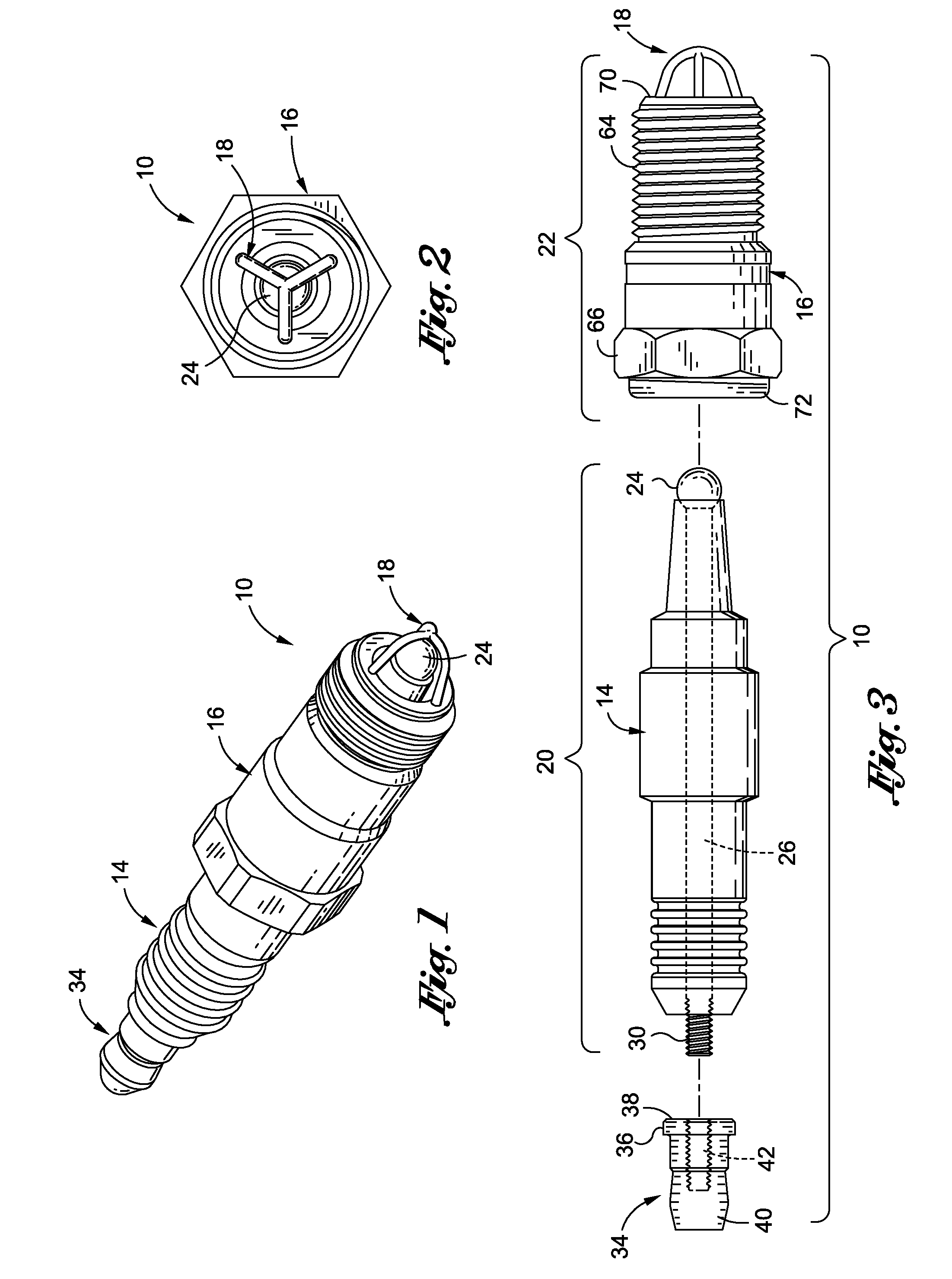
[0031]Referring now to the drawings, wherein the showings are for purposes of illustrating a preferred embodiment of the present invention only, and not for purposes of limiting the same, there is shown a method of manufacturing a spark plug 10 configured to mitigate misfire and improve gas mileage, peak engine performance, horsepower, and increases the RPM range of the vehicle. The manufacturing method allows for the economical formation of the uniquely configured spark plug components, as well as the unique assembly of the components to achieve the above-described performance of the spark plug 10.

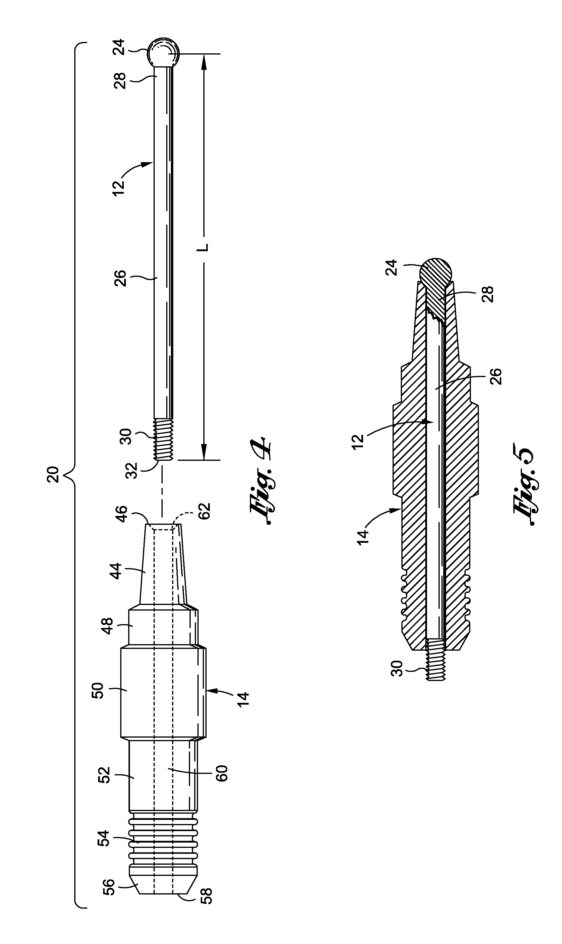
[0032]As described in more detail below, the spark plug 10 generally includes an electrode 12 (see FIG. 4), an insulator 14, a shell 16, and an electrode cage 18. During assembly of the spark plug10, the electrode 12 and insulator 14 are combined to form an insulator-electrode subassembly 20 (see FIG. 3), and the shell 16 and electrode cage 18 are combined to form a shell-cage subassembly...


PUM


Abstract

Provided is a manufacturing method for manufacturing a spark plug which produces a spark plug which mitigates misfire and improves gas mileage, peak engine performance, horsepower, and increases the RPM range of the host vehicle. The improved performance of the spark plug is, at least in part, attributable to the spacing between an electrode body and an electrode cage. In particular, the electrode cage extends over the electrode body such that the arcuate members of the electrode cage are equidistantly spaced from the bulbous or spherical electrode body. The manufacturing method described herein results in a spark plug having the above-described configuration, while being formed and assembled at an economical cost.

Description

CROSS-REFERENCE TO RELATED APPLICATIONS[0001]Not ApplicableSTATEMENT RE: FEDERALLY SPONSORED RESEARCH / DEVELOPMENT[0002]Not ApplicableBACKGROUND OF THE INVENTION[0003]1. Field of the Invention[0004]The present invention relates generally to spark plugs, and more specifically to a method of manufacturing a spark plug.[0005]2. Description of the Related Art[0006]Spark plugs are well-known in the art. A spark plug generally includes an elongated body having an electrical connector at one end. A pair of variable-spaced electrodes are typically provided at an opposing end, with one of the electrodes being electrically connected to the electrical connector.[0007]In most conventional spark plugs, one of the electrodes includes a cylindrical post while the second electrode is generally J-shaped and has a portion which overlies one end of the cylindrical post. Consequently, upon the application of voltage to the cylindrical post, a spark is formed between the end of the cylindrical post and t...

Claims


Application Information

Patent Timeline
Patent Type & Authority Applications(United States)
IPC IPC(8): H01T13/20H01T21/02
CPCH01T13/20H01T21/02H01T13/28
Inventor HILL, ALBERT SAM
Owner HKA INVESTMENTS
Learn More