Magnetic-balance-system current sensor

a current sensor and magnetic balance technology, applied in the field of magnetic balance system current sensor, can solve the problems of increasing the size of current sensor, and achieve the effect of high sensitivity

Active Publication Date: 2012-03-15
ALPS ALPINE CO LTD
View PDF0 Cites 54 Cited by
  • Summary
  • Abstract
  • Description
  • Claims
  • Application Information

AI Technical Summary

Benefits of technology

[0008]The present invention has been made in view of the above-described issues, and provides a magnetic-balance-system current sensor that can be miniaturized, and that also has a high sensitivity.
[0010]With this configuration, because the feedback coil, the magnetic cores, and the magnetic-field detecting bridge circuit are formed on the same substrate, the magnetic-balance-system current sensor can be miniaturized although the magnetic-balance-system current sensor has a structure having the magnetic cores. Accordingly, the magnitude of the cancelling magnetic field can be increased, and the measurement target current can be measured even when the measurement target current is a large current. Furthermore, because the magnetoresistive element is used as a magnetic detector element, the sensitivity of the current sensor can be increased.

Problems solved by technology

However, there is a problem that, when the size of magnetic cores is increased, the size of current sensors is also increased.

Method used


Image

  • Magnetic-balance-system current sensor
  • Magnetic-balance-system current sensor
  • Magnetic-balance-system current sensor

Examples


first embodiment

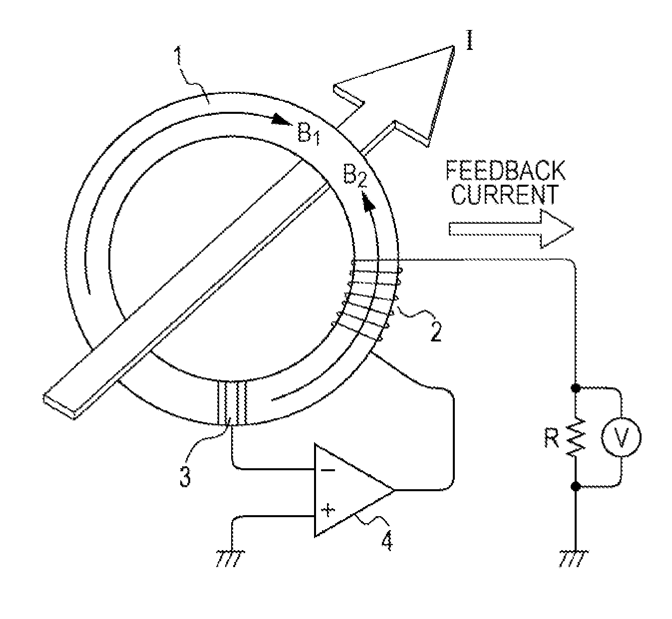
[0032]In a present embodiment, a case will be described, in which a feedback coil is of a toroidal type, and in which magnetic cores are provided inside the feedback coil.

[0033]FIG. 1 is a diagram of a magnetic-balance-system current sensor according to the first embodiment of the present invention. The magnetic-balance-system current sensor illustrated in FIG. 1 is disposed in the vicinity of a conductor 11 through which a measurement target current I flows. A feedback coil 12 is disposed so that a direction orthogonal to a direction in which the measurement target current I flows is an axial center direction X. The measurement target current I flows, thereby generating an induction magnetic field, and the feedback coil 12 generates a cancelling magnetic field that cancels out the induction magnetic field.

[0034]Furthermore, magnetic cores 13 are disposed so that an easy axis of magnetization is oriented in a direction Y (a direction that coincides with the current direction of the ...

second embodiment

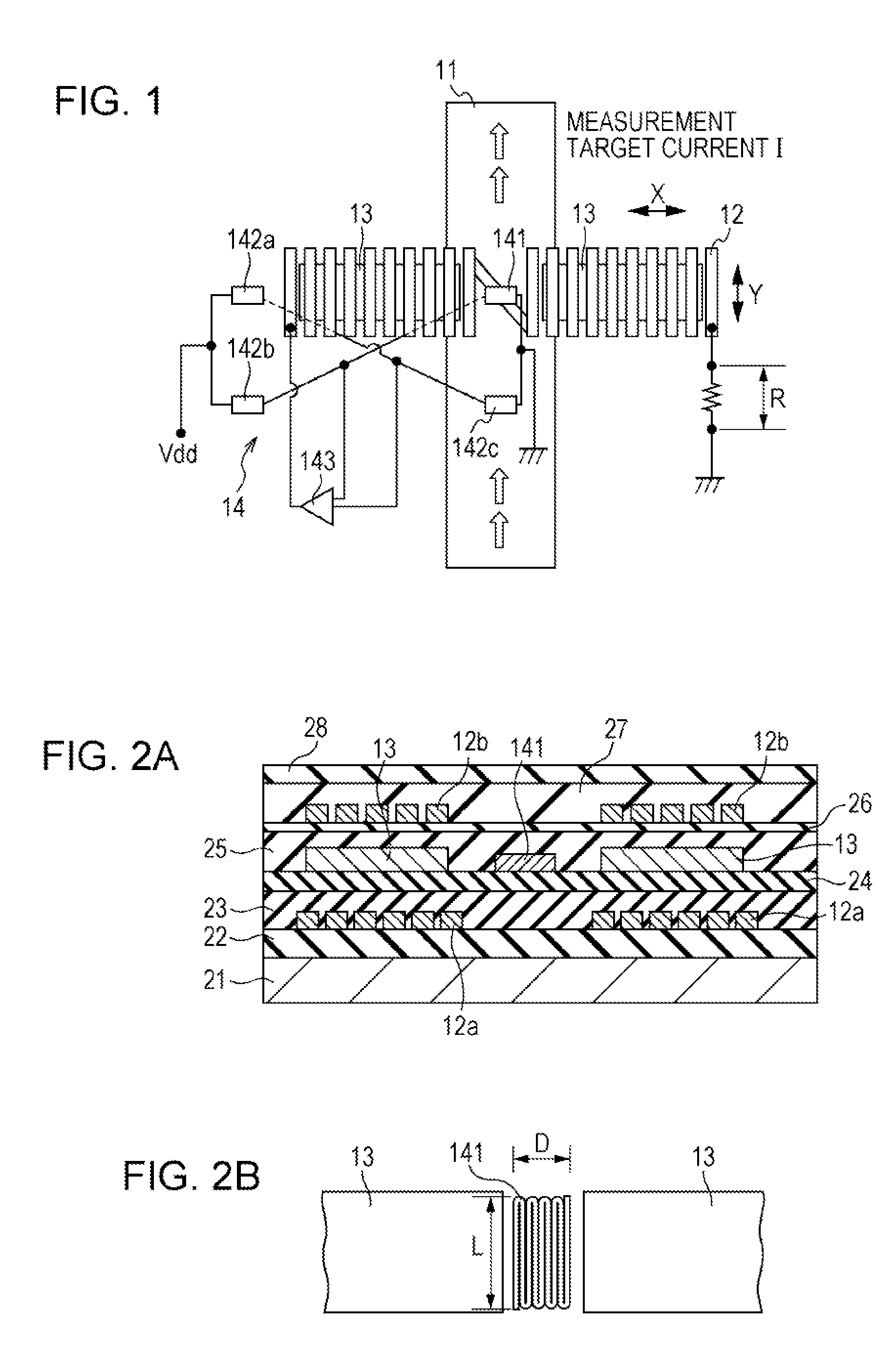
[0058]In a present embodiment, a case will be described, in which a feedback coil is of a spiral type, and in which magnetic cores are provided above and below the feedback coil.

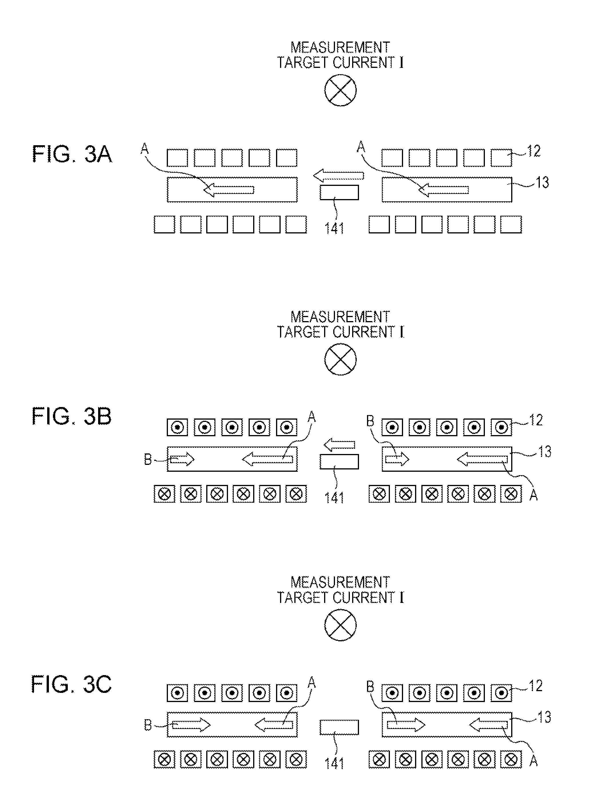
[0059]FIG. 8 is a diagram of a magnetic-balance-system current sensor according to the second embodiment of the present invention. FIG. 9 is a circuit diagram of the magnetic-balance-system current sensor illustrated in FIG. 8. The magnetic-balance-system current sensor illustrated in FIG. 8 is disposed in the vicinity of a conductor 11 through which a measurement target current I flows. A feedback coil (planar coil) 12 is disposed so that a direction orthogonal to a direction in which the measurement target current I flows is an axial center direction X. The measurement target current I flows, thereby generating an induction magnetic field, and the feedback coil 12 generates a cancelling magnetic field that cancels out the induction magnetic field.

[0060]Furthermore, magnetic cores 13 are disposed so that an...


PUM


Abstract

A magnetic-balance-system current sensor includes: a magnetoresistive element, a resistance value of the magnetoresistive element being changed by applying an induction magnetic field generated by a measurement target current; magnetic cores disposed near the magnetoresistive element; a feedback coil disposed near the magnetoresistive element and configured to generate a cancelling magnetic field that cancels out the induction magnetic field; and a magnetic-field detecting bridge circuit having two outputs. The measurement target current is measured on the basis of a current flowing through the feedback coil when the induction magnetic field and the induction magnetic field and the cancelling magnetic field cancel each other out. The feedback coil, the magnetic cores, and the magnetic-field detecting bridge circuit are formed on a same substrate. The feedback coil is of a spiral type, and the magnetic cores are provided above and below the feedback coil.

Description

CLAIM OF PRIORITY[0001]This application is a Continuation of International Application No. PCT / JP2010 / 059791 filed on Jun. 9, 2010, which claims benefit of Japanese Patent Application No. 2009-141707 filed on Jun. 12, 2009. The entire contents of each application noted above are hereby incorporated by reference.BACKGROUND OF THE INVENTION[0002]1. Field of the Invention[0003]The present invention relates to a magnetic-balance-system current sensor using a magnetoresistive element (a tunneling magnetoresistive element (TMR) element or a giant magnetoresistive element (GMR) element).[0004]2. Description of the Related Art[0005]Motors are driven using electricity generated by engines in electric vehicles. The magnitude of a current used to drive such a motor is detected by, for example, a current sensor. Such a current sensor is a sensor in which a magnetic core, a portion of which has a notch (a core gap), is disposed around a conductor, and in which a magnetic detector element is disp...

Claims


Application Information

Patent Timeline
Patent Type & Authority Applications(United States)
IPC IPC(8): G01R35/00
CPCB82Y25/00G01R33/093G01R33/04G01R15/205
Inventor IDE, YOSUKESAITO, MASAMICHITAKAHASHI, AKIRANOJIMA, TSUYOSHIMIYAJIMA, SHIGENOBUSAKATSUME, NAOKIICHINOHE, KENJINISHIYAMA, YOSHIHIROKOGURE, TATSUYAKOBAYASHI, HIDEKAZUIIZUKA, MASAHIRO
Owner ALPS ALPINE CO LTD
Why Eureka
Try Eureka