Magnetic balance type current sensor

Active Publication Date: 2012-03-15
ALPS ALPINE CO LTD
View PDF3 Cites 27 Cited by
  • Summary
  • Abstract
  • Description
  • Claims
  • Application Information

AI Technical Summary

Benefits of technology

[0021]The present invention provides a magnetic balance type current sensor including a magnetoresistance effect element whose resistance value changes owing to the application of an induction magnetic field from a current to be measured; a feedback coil disposed in the vicinity of the magnetoresistance effect element and generating a cancelling magnetic field cancelling out the induction magnetic field; a magnetic field detection bridge circuit including two outputs causing a voltage difference to occur, the voltage difference corresponding to the induction magnetic field; and a magnetic shield attenuating the induction magnetic fi

Problems solved by technology

However, in a magnetic balance type current sensor utilizing a magnetoresistance effect element without utilizing a magnetic material core, when the value of a current to be dealt wi

Method used


Image

  • Magnetic balance type current sensor
  • Magnetic balance type current sensor
  • Magnetic balance type current sensor

Examples


Example

First Embodiment

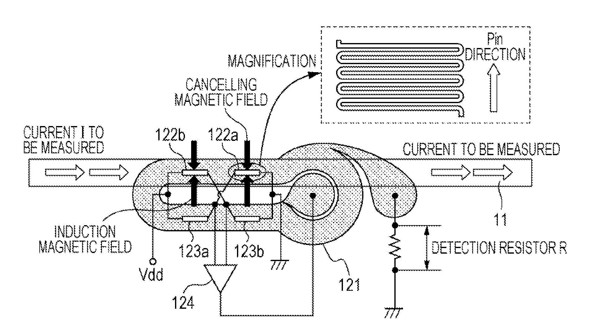
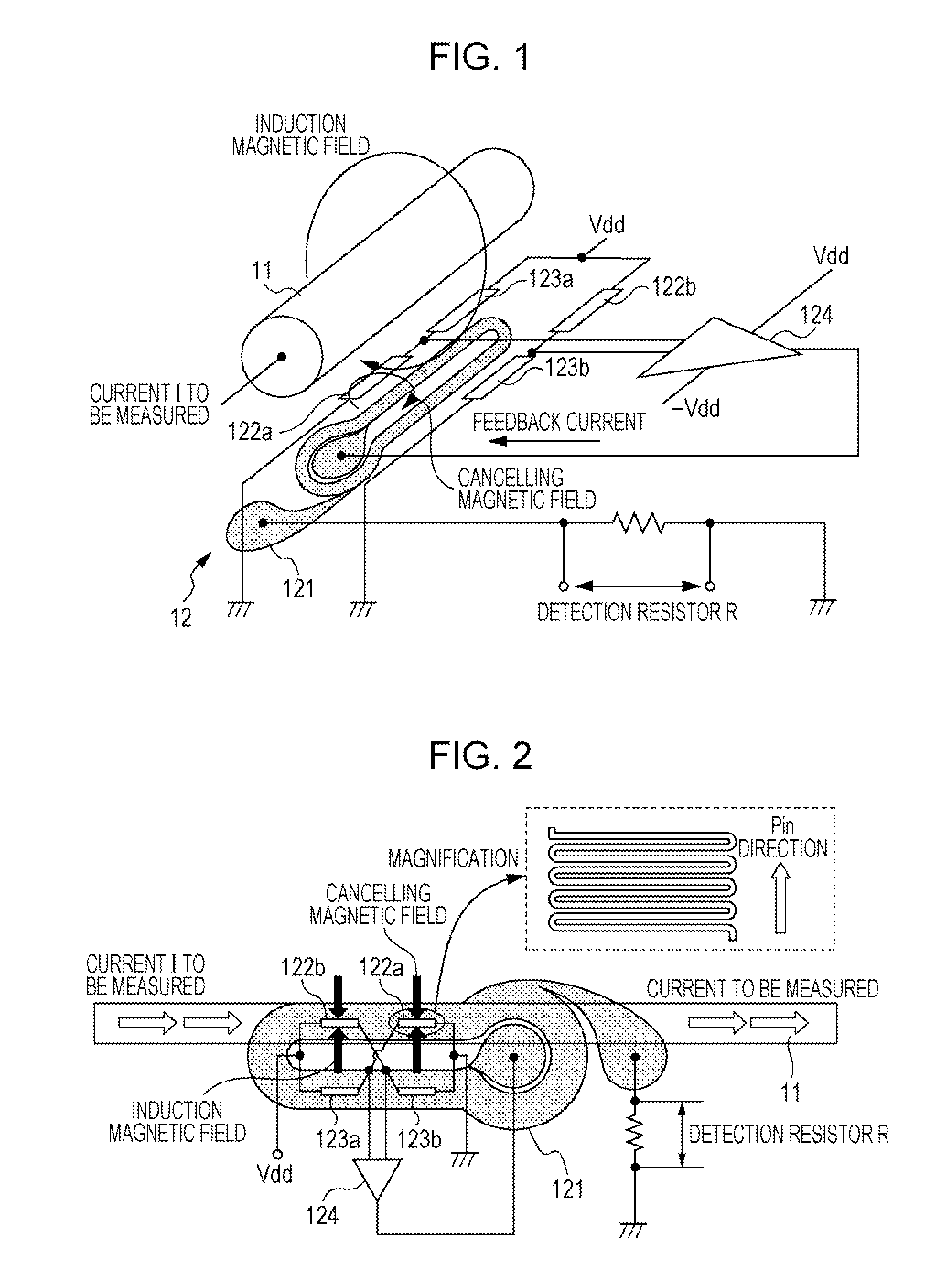
[0046]FIG. 1 and FIG. 2 are diagrams illustrating a magnetic balance type current sensor according to a first embodiment of the present invention. In the present embodiment, the magnetic balance type current sensor illustrated in FIG. 1 and FIG. 2 is arranged in the vicinity of a conductor 11 through which a current I to be measured flows. The magnetic balance type current sensor includes a feedback circuit 12 causing a magnetic field (cancelling magnetic field) to occur, the magnetic field cancelling out an induction magnetic field due to the current I to be measured flowing through the conductor 11. The feedback circuit 12 includes a feedback coil 121 wound in a direction cancelling out the magnetic field occurring owing to the current I to be measured, two magnetoresistance effect elements 122a and 122b that are magnetic detecting elements, and two fixed resistance elements 123a and 123b.

[0047]The feedback coil 121 is configured using a planar coil. In this confi...

Example

Second Embodiment

[0084]In the present embodiment, the case of a magnetic balance type current sensor will be described that includes a function in which a hysteresis is corrected when an output is measured in a state in which no current measurement is performed and the output is different from a reference output.

[0085]In the magnetic balance type current sensor, when a current to be measured exceeding the measurement range of a sensor flows, it is difficult to achieve a magnetic equilibrium. In particular, in a case in which the magnetic detecting element is a magnetoresistance effect element, since, as illustrated in FIG. 14A, the element has a hysteresis characteristic, when the current to be measured is large, the magnetoresistance effect element is saturated and a zero point deviates owing to the hysteresis of the element. As a result, as illustrated in FIG. 14B, the characteristic curve of an output with respect to an input current deviates to a + side or a − side, and it may b...

Example

Third Embodiment

[0091]In the present embodiment, a magnetic balance type current sensor will be described that includes a function in which the self-test of the magnetoresistance effect element is performed by passing a current through a calibration coil in a state in which no input of a current exists.

[0092]When the induction magnetic field occurring from the current to be measured is measured using a magnetic balance type sensor, it is likely that the magnetoresistance effect element is influenced by an external magnetic field owing to another element or a wiring line in addition to the conductor through which the current to be measured flows. In addition, when high reliability is necessary as in automobiles, it may be likely that a serious accident is invited if the output of the magnetoresistance effect element with respect to the input current changes owing to some factor.

[0093]FIG. 18 is a diagram illustrating part of the magnetic balance type current sensor according to the p...


PUM


Abstract

A magnetic balance type current sensor includes a magnetoresistance effect element whose resistance value changes owing to the application of an induction magnetic field from a current to be measured; a feedback coil disposed in the vicinity of the magnetoresistance effect element and generating a cancelling magnetic field cancelling out the induction magnetic field; a magnetic field detection bridge circuit including two outputs causing a voltage difference corresponding to the induction magnetic field to occur; and a magnetic shield attenuating the induction magnetic field and enhancing the cancelling magnetic field, wherein, on the basis of the current flowing through the feedback coil at the time of an equilibrium state in which the induction magnetic field and the cancelling magnetic field are cancelled out, the current to be measured is measured, wherein the feedback coil, the magnetic shield, and the magnetic field detection bridge circuit are formed on a same substrate.

Description

CLAIM OF PRIORITY[0001]This application is a Continuation of International Application No. PCT / JP2010 / 059959 filed on Jun. 11, 2010, which claims benefit of Japanese Patent Application No. 2009-141706, filed on Jun. 12, 2009. The entire contents of each application noted above are hereby incorporated by reference.BACKGROUND OF THE INVENTION[0002]1. Field of the Invention[0003]The present invention relates to a magnetic balance type current sensor utilizing a magnetoresistance effect element (TMR element or GMR element).[0004]2. Description of the Related Art[0005]In an electric automobile, a motor is driven using electricity generated by an engine, and the intensity of a current used for driving the motor is detected by, for example, a current sensor. The current sensor includes a magnetic core placed around a conductor and having a cutaway portion (core gap) formed at a portion thereof, and a magnetic detecting element placed in the core gap. As such a current sensor, for example, ...

Claims


Application Information

Patent Timeline
IPC IPC(8): G01R33/02
CPCB82Y25/00G01R15/205G01R33/093G01R33/04G01R31/006
Inventor IDE, YOSUKEIIZUKA, MASAHIROSAITO, MASAMICHITAKAHASHI, AKIRAMATSUO, HIDEHARUNOJIMA, TSUYOSHIMIYAJIMA, SHIGENOBUSAKATSUME, NAOKIICHINOHE, KENJINISHIYAMA, YOSHIHIROKOGURE, TATSUYAKOBAYASHI, HIDEKAZU
Owner ALPS ALPINE CO LTD
Why Eureka
Try Eureka