Unlock instant, AI-driven research and patent intelligence for your innovation.

Flake coil

a flake coil and coil body technology, applied in the field of flake coils, can solve the problems of coil breakage and aging, high manufacturing cost, complicated and time-consuming coil manufacturing, etc., and achieve the effect of simple flake coil manufacturing process, increased efficiency per unit volume, and greater current outpu

Inactive Publication Date: 2012-03-15
LAI PING LI
View PDF8 Cites 0 Cited by
  • Summary
  • Abstract
  • Description
  • Claims
  • Application Information

AI Technical Summary

Benefits of technology

[0011]The flake coil of the present invention can be used instead of the conventional coil made of small-diameter wire materials by winding. The manufacturing process of the flake coil is simpler and the flake coil is not subject to breakage. Moreover, the flake coil is able to achieve and bear greater current output so that the efficiency per unit volume is increased.

Problems solved by technology

The number of turns in the coil wound around the seat body is very large so that it is complicated and time-consuming to manufacture the coil.
As a result, the manufacturing cost is relatively high.
Therefore, when transmitting great current, the coil is subject to breakage and aging.
As a result, the generator or the motor is very likely to damage.
In this case, the magnetic fields will offset each other to lead to poor magnetic efficiency.
In the case that it is unnecessary to dispose any iron core in the hollow section of the coil, the hollow section will unnecessarily occupy much area and space.
This leads to a considerably large volume of the coil.

Method used


Image

  • Flake coil
  • Flake coil
  • Flake coil

Examples


Embodiment Construction

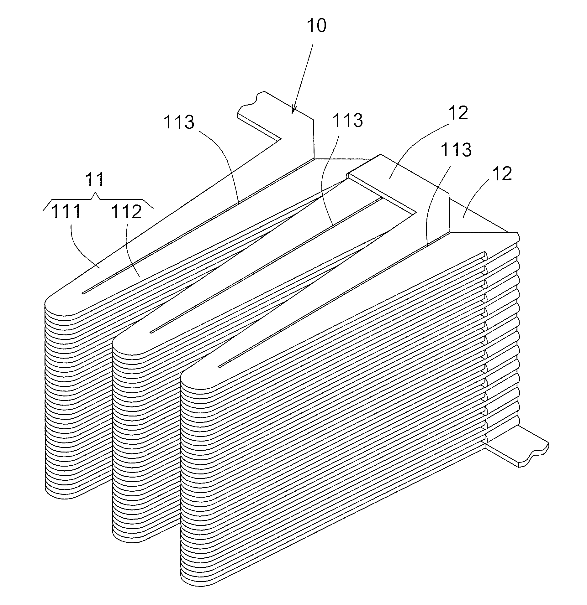
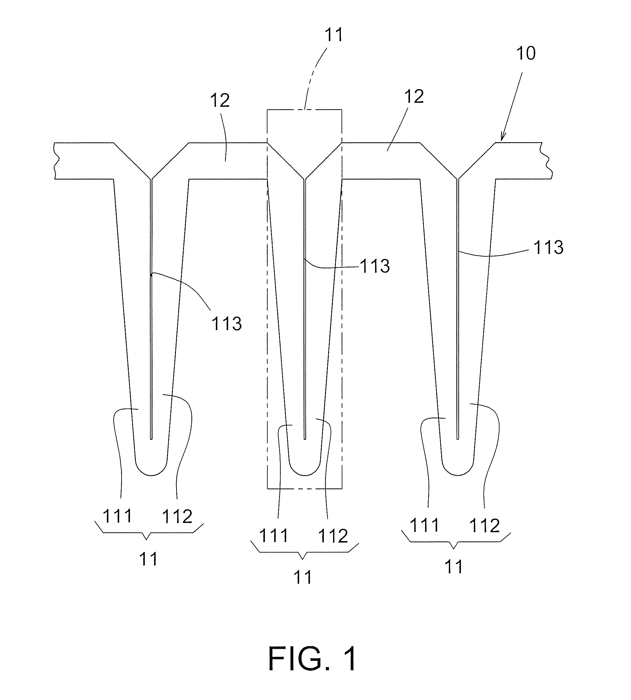
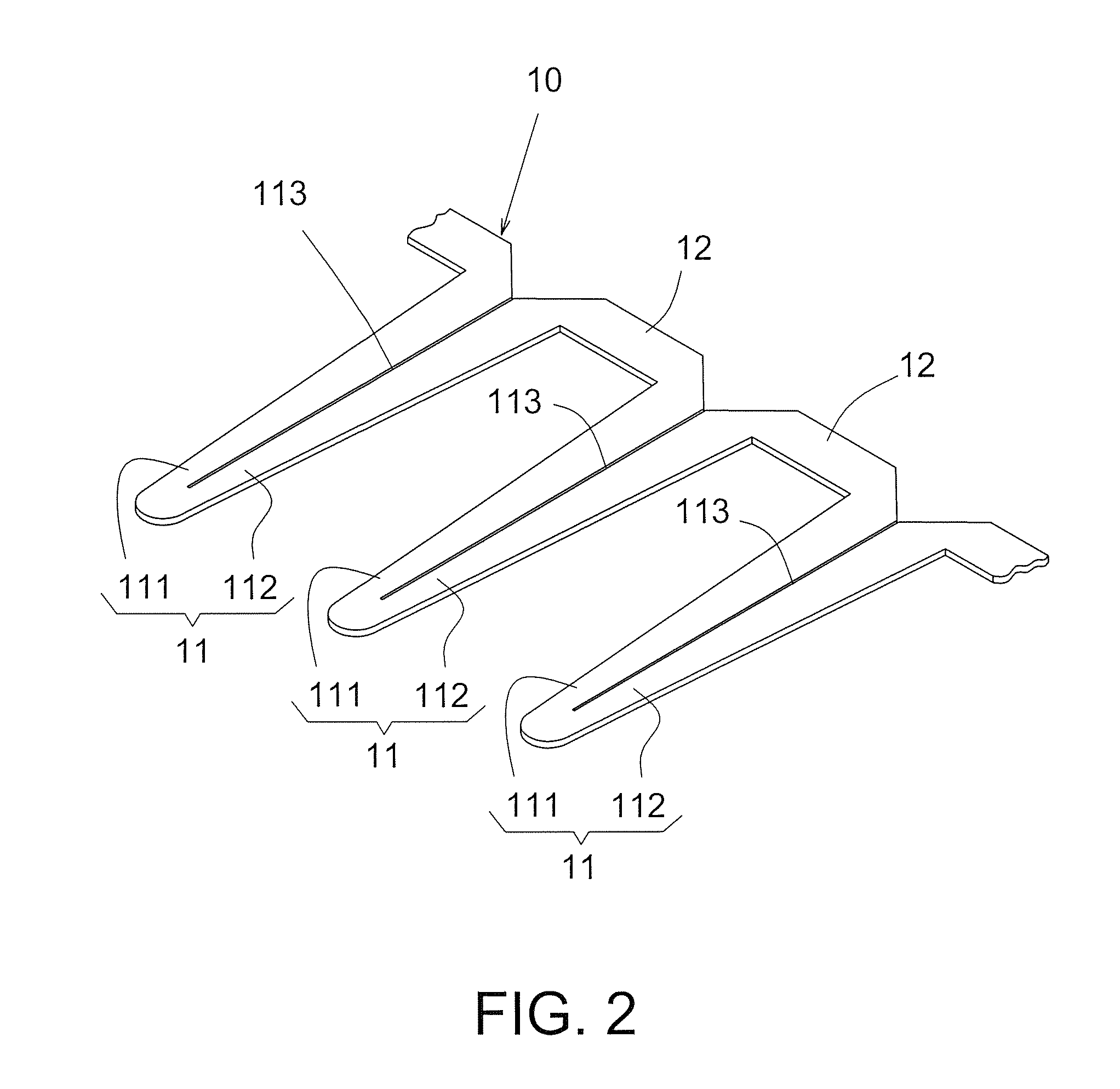
[0022]Please refer to FIGS. 1 to 5. The flake coil 10 of the present invention is integrally made of a conductive material coated with an insulation layer. The flake coil 10 includes multiple coil units 11, which are sequentially stacked. Each coil unit 11 has a first coil section 111 and a second coil section 112. The first and second coil sections 11, 112 are arranged side by side. A split 113 is defined between the first and second coil sections 111, 112. A first end of the first coil section 111 is integrally connected with a first end of the second coil section 112. A second end of the first coil section 111 is integrally connected with a second end of the second coil section 112 of an adjacent coil unit 11 via a connection board section 12. The connection board section 12 is bent back over itself to stack the coil units 11. Accordingly, the coil units 11 are continuously stacked to form multiple stacks of coil units 11 for one-way transmitting current. The flake coil 10 is app...


PUM


Abstract

A flake coil integrally made of a conductive material coated with an insulation layer. The flake coil includes multiple coil units, which are sequentially stacked. Each coil unit has a first coil section and a second coil section, which are arranged side by side. A split is defined between the first and second coil sections. A first end of the first coil section is integrally connected with a first end of the second coil section. A second end of the first coil section is integrally connected with a second end of the second coil section of an adjacent coil unit via a connection board section. The connection board section is bent back over itself to stack the coil units. Accordingly, the coil units are continuously stacked to form multiple stacks of coil units for one-way transmitting current. The flake coil is applicable to a generator or a motor.

Description

BACKGROUND OF THE INVENTION[0001]1. Field of the Invention[0002]The present invention relates generally to a flake coil, and more particularly to an integrally formed flake coil including multiple coil units. A connection board section is connected between each two adjacent coil units. The connection board section is bent back over itself to stack the coil units. Accordingly, the coil units are continuously stacked to form multiple stacks of coil units.[0003]2. Description of the Prior Arts The conventional coil applied to a generator or a motor is generally made of a wire material wound around a seat body. When magnetic lines pass through the coil, a potential is induced to generate current passing through the coil. Such coil is applicable to a generator to generate power. Alternatively, a current can pass through the coil to magnetize an iron core enclosed in the coil so as to create an electromagnetic field. Such coil is applicable to a motor.[0004]The number of turns in the coil...

Claims


Application Information

Patent Timeline
IPC IPC(8): H01F27/28
CPCH02K3/47H02K3/04
Inventor LAI, PING-LI
Owner LAI PING LI