
A power supply circuit applied to a TV set and the TV set

A technology for power supply circuits and televisions, which is applied in the field of televisions and can solve problems such as large output current, inability to conduct, and inability to charge portable devices

Active Publication Date: 2018-10-12
HISENSE VISUAL TECH CO LTD
View PDF7 Cites 0 Cited by
  • Summary
  • Abstract
  • Description
  • Claims
  • Application Information

AI Technical Summary

Problems solved by technology

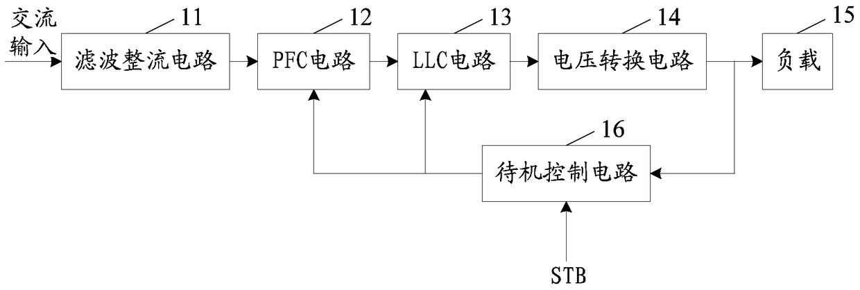
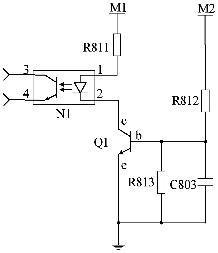
Specifically, when in the normal standby state, the entire power supply circuit starts from the AC input, and outputs the standby voltage Vt through the filter rectifier circuit 11, the PFC circuit 12, the LLC circuit 13, and the voltage conversion circuit 14 to provide the load 15 for use; at the same time, Since in the normal standby state, the output terminal of the external signal device has no signal output, that is, there is no STB signal output, therefore, no voltage is applied to the base b of the transistor Q1, so that the collector c and the emitter e of the transistor Q1 cannot be turned on , and then make the anode 1 and cathode 2 of the photocoupler N1 unable to conduct, therefore, the collector 3 and emitter 4 of the photocoupler N1 have no signal output, that is, in the normal standby state, the standby control circuit 16 does not work
In addition, the power supply circuit in the standby state can only provide a small output current to meet the mandatory low power consumption standby requirements of various countries (less than 0.5W), but cannot provide a large output current, and thus cannot realize the power consumption in the standby state. Charging and other functions for portable devices, reducing user experience

Method used


Image

  • A power supply circuit applied to a TV set and the TV set
  • A power supply circuit applied to a TV set and the TV set
  • A power supply circuit applied to a TV set and the TV set

Examples


Embodiment Construction

[0024] The following will clearly and completely describe the technical solutions in the embodiments of the present invention with reference to the accompanying drawings in the embodiments of the present invention. Obviously, the described embodiments are only some, not all, embodiments of the present invention. Based on the embodiments of the present invention, all other embodiments obtained by persons of ordinary skill in the art without creative efforts fall within the protection scope of the present invention.

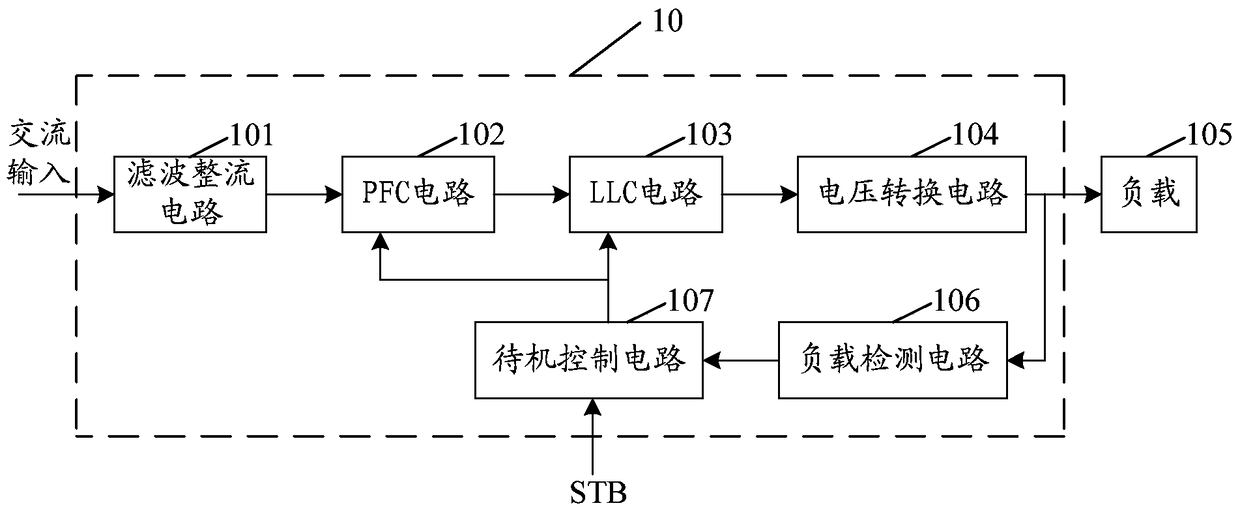
[0025] An embodiment of the present invention provides a power supply circuit, which is applied in a television. Such as image 3 As shown, the power supply circuit 10 includes a filter rectifier circuit 101, a power factor correction (Power Factor Correction, PFC for short) circuit 102, an LLC circuit 103, and a voltage conversion circuit 104 connected in sequence, and the output terminal of the voltage conversion circuit 104 is used to communicate with the load ...


PUM


Abstract

The embodiment of the invention provides a power supply circuit applied to a television set and a television set, which is used for providing enough current when the television set stays at a standby state, thus realizes a function of charging an external portable device and improves the user experience. The power supply circuit comprises a filtering and rectification circuit, a power factor correction (PFC) circuit, a resonant LLC circuit and a voltage conversion circuit which are sequentially connected, wherein the output end of the voltage conversion circuit is used for being connected with a load. The power supply circuit further comprises a load detection circuit and a standby control circuit, wherein the load detection circuit is used for outputting feedback signals to the standby control circuit when the load is detected to increase, the operating states of the PFC circuit and the LLC circuit are adjusted through the standby control circuit, and output current of the LLC circuit is enabled to increase. The power supply circuit provided by the embodiment of the invention is applied to the television set.

Description

technical field [0001] The invention relates to the technical field of televisions, in particular to a power supply circuit applied to televisions and the television. Background technique [0002] With the continuous development of electronic technology and the continuous increase of people's needs, electrical equipment with various functions has been gradually developed, making people's lives more convenient and convenient. Wherein, television set has become one of requisite electronic equipment in people's life. [0003] Since the TV will generate a certain amount of energy consumption in both the playing state and the standby state, and as the size of the TV screen gradually increases, the energy consumption will also increase, and the increase in energy consumption will lead to a decrease in user expenses. Increase. In order to reduce energy consumption, one of the main means adopted in the prior art is to improve the working efficiency of the TV power supply. However...

Claims


Application Information

Patent Timeline
Patent Type & Authority Patents(China)
IPC IPC(8): H04N5/63H04N21/426
Inventor 刘海丰
Owner HISENSE VISUAL TECH CO LTD
Learn More