Microscope apparatus and observation method

a microscope and apparatus technology, applied in the field of microscope apparatus and observation method, can solve the problem of not being able to obtain high-resolution pictures, and achieve the effect of high resolution

Active Publication Date: 2012-03-15
NIKON CORP
View PDF19 Cites 48 Cited by
  • Summary
  • Abstract
  • Description
  • Claims
  • Application Information

AI Technical Summary

Benefits of technology

[0017]According to the microscope apparatus and observation method pertaining to the aspects of the present invention, picture images

Problems solved by technology

With respect to the conventional observation method, in the case where multiple regions with markedly different densities of fluorescent material exist within the same view field, a picture i

Method used


Image

  • Microscope apparatus and observation method
  • Microscope apparatus and observation method
  • Microscope apparatus and observation method

Examples


first embodiment

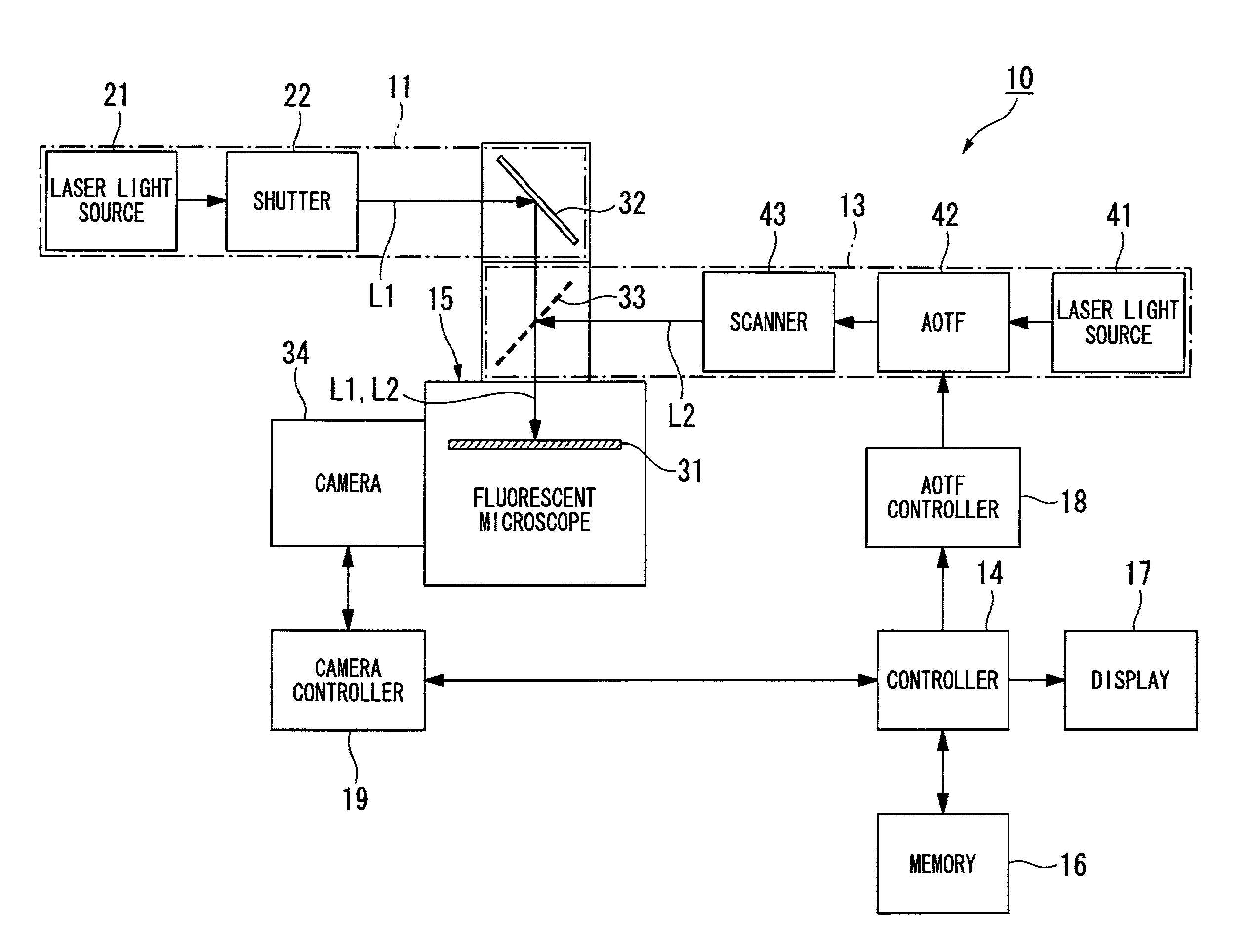
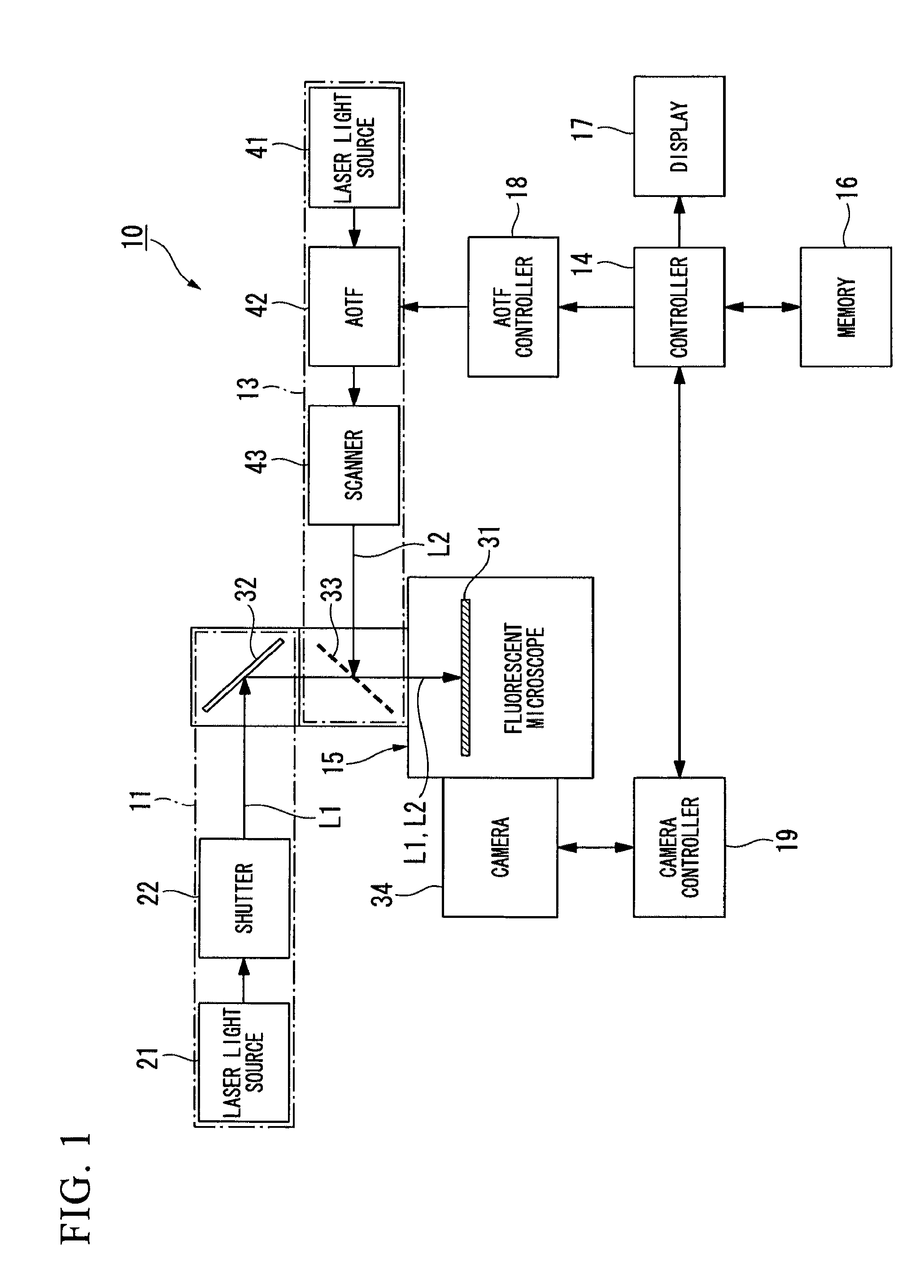
[0033]FIG. 1 is a schematic view which shows a microscope apparatus pertaining to a first embodiment.

[0034]A microscope apparatus 10 is provided with a microscope body 15, an excitation illumination system 11 attached to the microscope body 15, an activation illumination system 13, a controller 14, a memory 16, and a display 17.

[0035]The microscope apparatus 10 is a microscope apparatus which uses super-resolution microscopy (stochastic optical reconstruction microscopy: STORM).

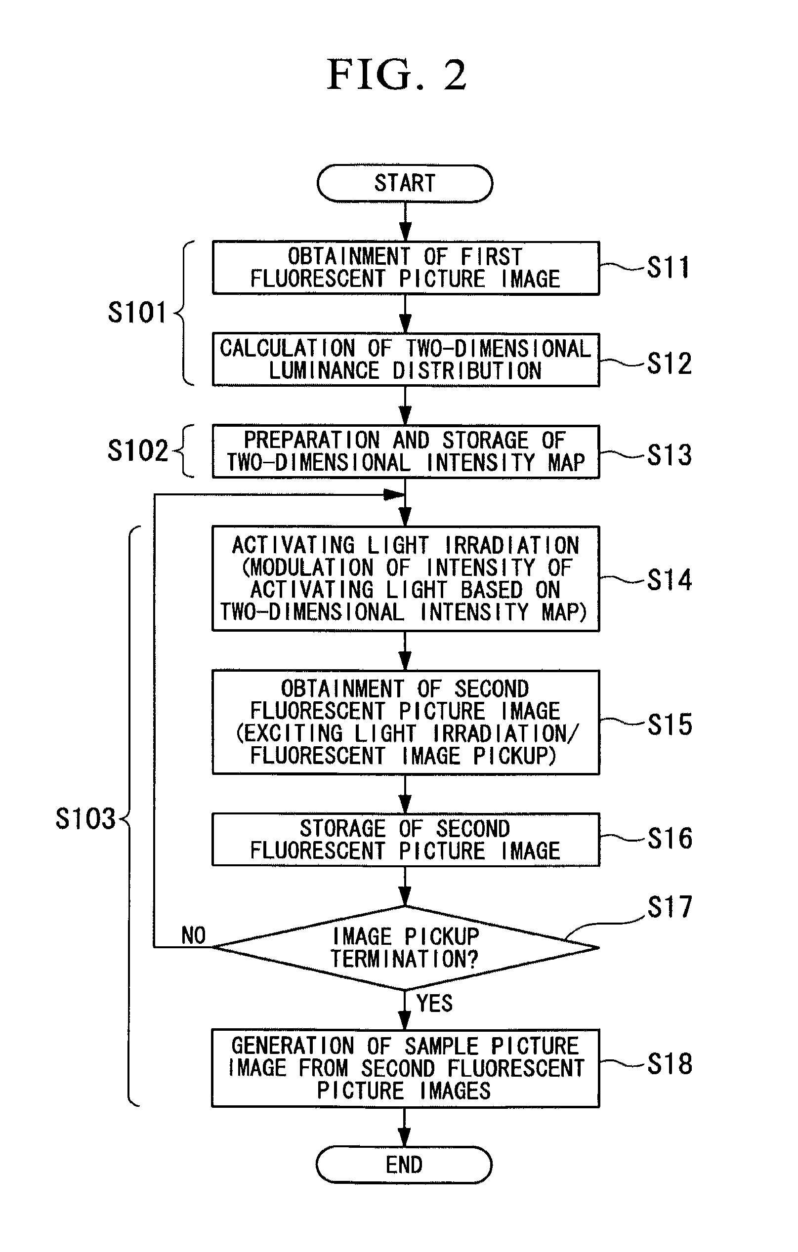
[0036]In the microscope apparatus 10, a sample is used which is provided with inactive fluorescent material as a label that is activated when irradiated with activating light L2 of a prescribed wavelength, and that emits fluorescence when irradiated in an activated condition with exciting light L1 of a wavelength that differs from the activating light L2. Using the excitation illumination system 11 and the activation illumination system 13, one repeats operations wherein discretely distributed fluorescence is...

second embodiment

[0123]FIG. 8 is a schematic view which shows the microscope apparatus of a second embodiment. Components that are common to the first embodiment are assigned the same reference numbers in FIG. 8, and detailed description thereof is omitted.

[0124]A microscope apparatus 60 of the second embodiment is configured so as to be provided with an activation illumination system 63, instead of the activation illumination system 13 of the first embodiment. The activation illumination system 63 is provided with a mercury lamp 61, a spatial light modulator 62, and the dichroic mirror 33, and is connected to the microscope body 15 via the dichroic mirror 33. The spatial light modulator 62 is connected to a light modulation controller 68, and the light modulation controller 68 is connected to the controller 14.

[0125]The spatial light modulator 62 is, for example, a DMD (Digital Mirror Device; registered trademark) or a liquid crystal panel. A DMD is provided with a configuration wherein numerous mi...

third embodiment

[0129]In the foregoing embodiments, the descriptions concerned a microscope apparatus which uses two lasers with different wavelengths for activation and excitation. On the other hand, dSTORM (direct Stochastic Optical Reconstruction Microscopy) is known as a super-resolution microscope technology that uses only a single short-wavelength laser (e.g., paper: Applied Physics B (2008)93: 725-731, Photoswitching Microscopy with Standard Fluorophores, S. van de Linde, R. Kasper, M. Heilemann, M. Sauer). With respect to dSTORM, there is no irradiation with an activation-use laser as in conventional STORM, and a picture image with only a small number of fluorochromes is obtained based on spontaneous flickering of the fluorescent material.

[0130]The fluorescent microscope apparatus of the third embodiment is configured to apply this dSTORM.

[0131]As the microscope apparatus of the third embodiment, one may adopt a configuration which omits the activation illumination system 13 from the micros...


PUM


Abstract

A microscope apparatus comprises: a distribution measurement apparatus with respect to an observation region that comprises a fluorescent material that is activated when irradiated with an activating light, and that emits fluorescence when irradiated with an exciting light of a wavelength different from the activating light, obtains a fluorescent picture image through irradiation with the exciting light, and measures a fluorescent intensity distribution; an irradiation intensity setting apparatus which sets irradiation intensities of the activating light for respective portions of the observation region based on the fluorescent intensity distribution; and a picture image formation apparatus which obtains a plurality of the fluorescent picture images by repeating an operation wherein the observation region is irradiated with the activating light at the set irradiation intensities, and repeating an operation wherein a fluorescent picture image is obtained by irradiating with the exciting light after the activating light irradiation, generating a sample picture image.

Description

CROSS-REFERENCE TO RELATED APPLICATION[0001]Priority is claimed on Japanese Patent Application No. 2010-134217, filed on Jun. 11, 2010, the contents of which are incorporated herein by reference.BACKGROUND[0002]1. Field of the Invention[0003]The present invention relates to a microscope apparatus and an observation method.[0004]2. Description of Related Art[0005]Previously, as a super-resolution microscope, STORM (Stochastic Optical Reconstruction Microscopy) has been known (e.g., see US Patent Publication No. 2008 / 0032414). With this microscope, as an observation sample, one uses fluorescent material or an object to which this fluorescent material adheres which is activated when irradiated with activating light of a prescribed wavelength, and which has the property of becoming inactive by emitting fluorescence when subsequently irradiated with exciting light of a wavelength that differs from the activating light. With respect to this type of observation sample, the fluorescent mate...

Claims


Application Information

Patent Timeline
IPC IPC(8): H04N7/18
CPCG01N21/6458G02B21/06G02B27/56G02B21/367G02B21/16
Inventor SASE, ICHIRO
Owner NIKON CORP
Why Eureka
Try Eureka