
Contact Lens and Method of Manufacture

a technology of contact lenses and lenses, which is applied in the field of contact lenses and methods of manufacture, can solve the problems that the front surface of the contact lens cannot be affected, the distortion of the optics cannot be satisfactorily corrected by spectacles, and the deformation of the optics cannot be transferred to the front surface of the contact lens, so as to achieve the effect of keeping the optical zone of the contact lens relatively thin

Active Publication Date: 2012-03-15
CONTACT LENS PRECISION LAB
View PDF2 Cites 5 Cited by
  • Summary
  • Abstract
  • Description
  • Claims
  • Application Information

AI Technical Summary

Benefits of technology

[0022]defining one or more positions or loci within the peripheral zone of the lens, and adjusting the sagittal depth of the lens at the one or more defined positions or loci so as to improve the fit of the peripheral zone of the lens to the subject's cornea.
[0054]The present invention allows the design of lenses with a thinner optical zone, by optimising the fit of the peripheral zone of the lens to the subject's cornea, such that the overall sagittal thickness of the lens (especially at the junction of the optic and peripheral zones) can be closer to that of the typical trial lens (about 0.4 mm) and thus deviates less from the fit expected as a result of the findings from the trial lens.

Problems solved by technology

This bulging of the cornea causes it to depart from the ideal asphericity, and so causes defective vision.
Keratoconic visual defects cannot be satisfactorily corrected by spectacles.
This conventional method therefore relies on a contact lens being rigid enough to support itself over the distortions of the cornea, resisting the capillary forces of the tear layer, and not allowing these distortions to be transferred to the front surface of the contact lens.
However, the requirement that the contact lens needs to be rigid, coupled with the abnormal distortion of the cornea, means that the fitting of such rigid lenses for subjects of this sort is extremely difficult.
This is clearly inefficient, expensive and time-consuming, and can cause a lot of discomfort for the subject.

Method used


Image

  • Contact Lens and Method of Manufacture
  • Contact Lens and Method of Manufacture
  • Contact Lens and Method of Manufacture

Examples


example 2

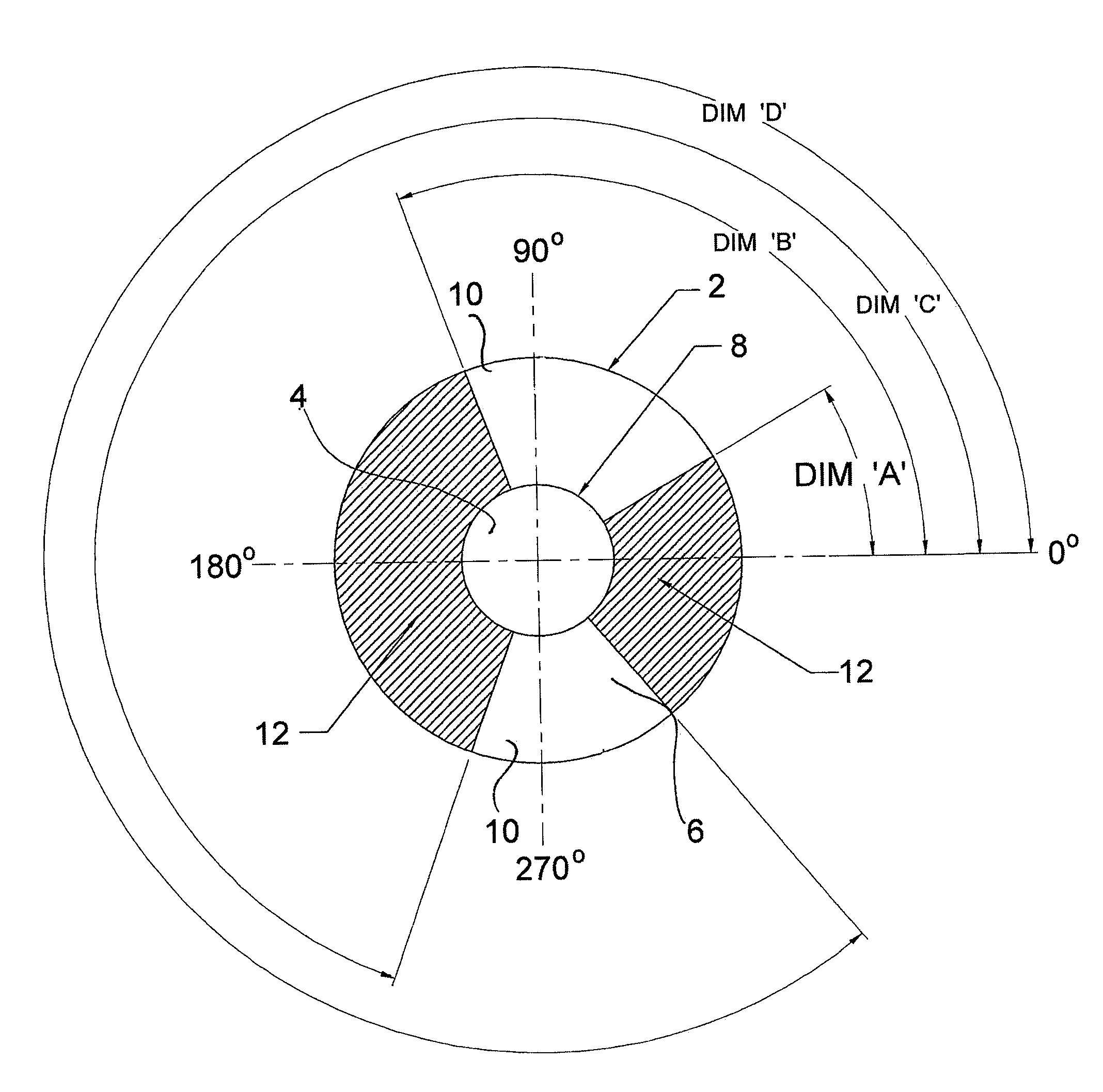
[0080]This example describes a preferred feature of the invention, (“sector management control”), in which the sagittal depth of the peripheral zone of the lens is adjusted to improve the fit of the peripheral zone of lens to a subject's cornea.

[0081]Referring to FIG. 5, a lens (2) comprises a central, circular optic zone (4) and a peripheral zone (6) disposed around the optic zone, the junction between the central zone (4) and the peripheral zone (6) denoted by reference numeral (8). The angular position of positions around the lens is conventionally defined by reference to a horizontal line passing through the centre of the lens, with O° at the right hand end of the horizontal line.

[0082]The peripheral zone of the lens is divided into two sectors (10) of default sagittal depth, and two sectors (12), shown shaded, with have a sagittal depth which may be greater or less than the default depth. An optometrist or other individual provided with information regarding the shape of the su...

example 3

[0085]This example illustrates an advantage of the invention. FIG. 8 is a transverse medial section through a conventional afocal trial lens used for test fitting purposes. In the optic zone (26), the front and near surfaces of the lens are of equal radius of curvature, so there is not net refraction.

[0086]FIG. 9 is a transverse medial section through a conventional prior art lens of high optical power. As a result of the larger radius of curvature applied to the front surface of the optic zone (26), the sagittal depth of the peripheral zone of the lens (28) is significantly thicker than that of the peripheral zone (28) of the test lens (depicted in FIG. 8). As a result, the corrective lens may not fit the subject as well as would be expected from the analysis performed using the trial lens. (“Fit”, in this context, also encompassing the interaction between the lens and the subject's eyelids).

[0087]FIG. 10 shows a transverse medial section through a corrective lens designed in accor...

example 4

[0088]History

[0089]KB is a 28 year old male. He had been considered amblyopic in the right eye for many years until he was diagnosed with keratoconus in 2009, when he sought help as his left eye began to deteriorate. Six months prior to his appointment he had attempted to wear RGP lenses, but discontinued due to intolerance and had managed with spectacles since that time. The keratoconus in his left eye had been actively progressing for six months and he was therefore considering CXL treatment for this eye.

[0090]Initial Findings

[0091]Spectacle Refraction

[0092]RE: −4.00 / −4.25×55 VA 6 / 60 LE: −5.50−5.00×101 6 / 18

[0093]As KB suffers from ghosting and multiple images with spectacle wear, he has difficulties viewing computer screens.

[0094]Previous Contact Lens Prescription:

[0095]RE: 6.77×31 / 5.78×121

[0096]LE: 7.18×153 / 7.02×7.02×63

[0097]Slit Lamp

[0098]Cornea clear both eyes. No staining with fluorescein.

[0099]Rationale for Fitting Contact Lens of the Invention

[0100]Patient preference was for...


PUM


Abstract

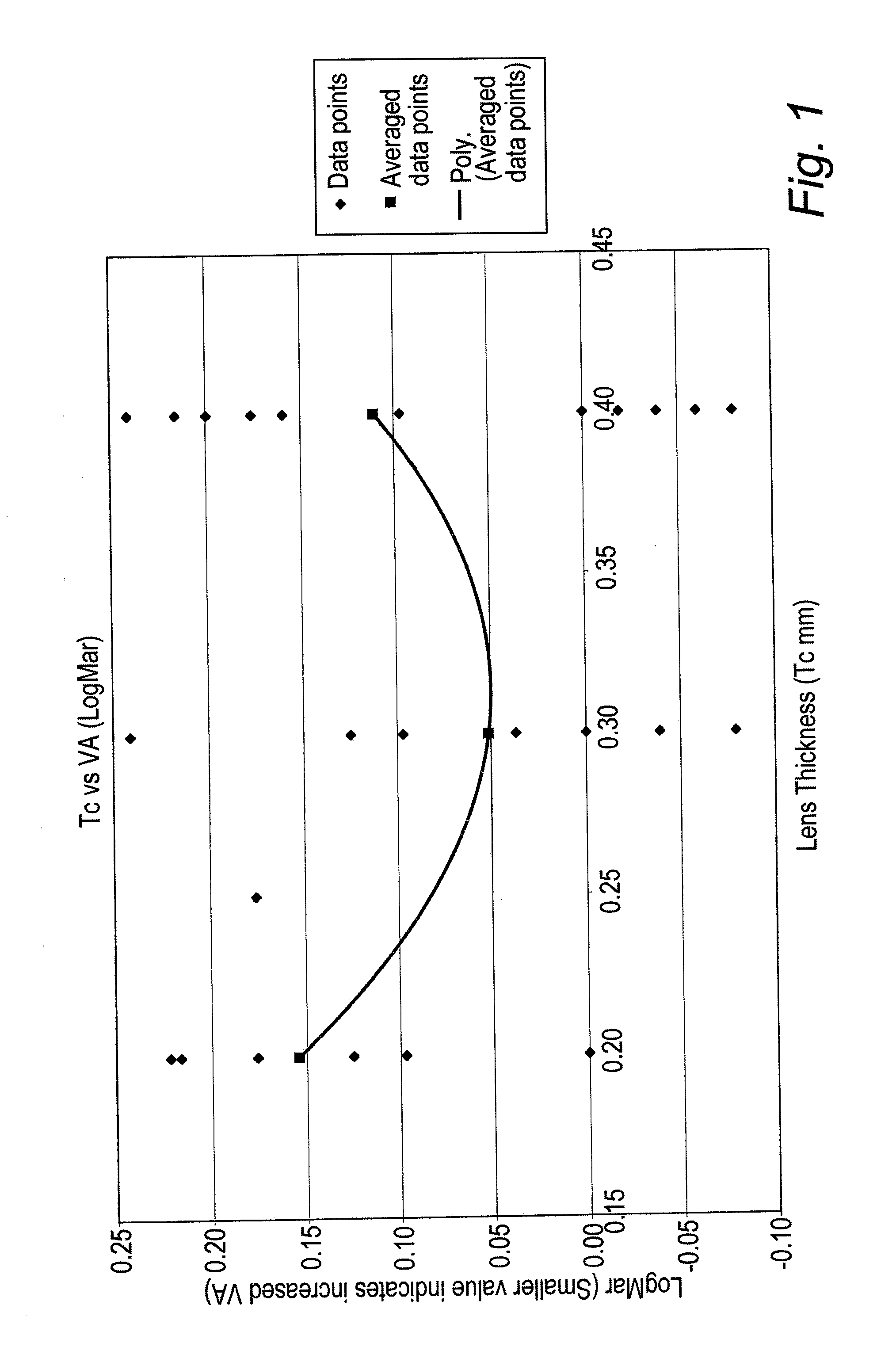
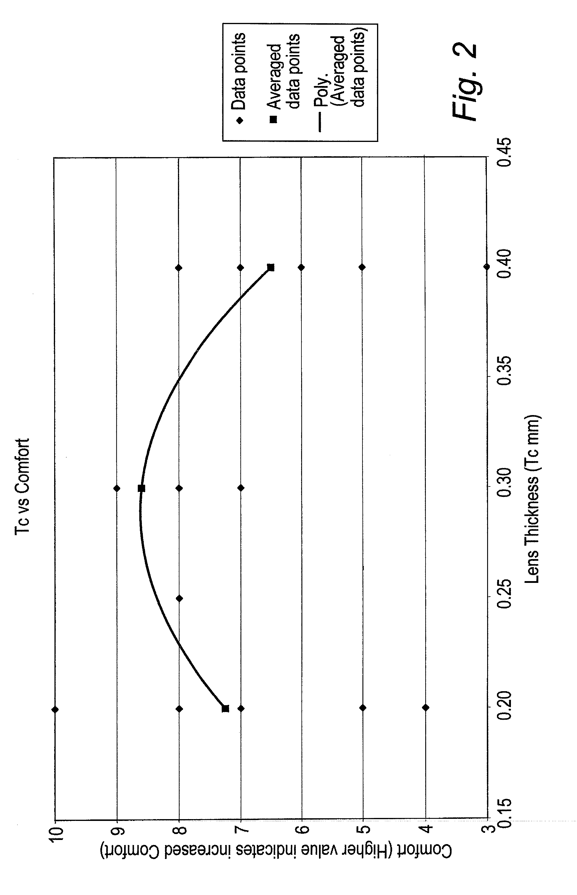
The invention relates to a method of designing a soft contact lens, said lens having a central optic zone and with a peripheral zone around the central optic zone; the method comprising the steps of:(a) defining a back surface of the lens which is a satisfactory fit to the surface of a subject's cornea;(b) defining a front surface of the lens over at least the central optic zone, which surface is selected so as to ameliorate the subject's vision defects;(c) checking that the lens meets a desired range of thickness values at one or more selected parts of the lens and, if not, recalculating the front surface over at least the central optic zone so as to meet said desired thickness value range,wherein the lens is to be made of a substance having a Young's modulus in the range 0.08 to 0.40 MPa, and wherein the junction thickness of the lens is in the range 0.15-0.40 mm.

Description

FIELD OF THE INVENTION[0001]This invention relates to a method of designing and of manufacturing a contact lens, and to a contact lens manufactured by the method.BACKGROUND OF THE INVENTION[0002]Defects in vision include myopia, hypermetropia and astigmatism. These are all very common defects, and are readily correctable by spectacles or contact lenses, which may be “rigid” or “soft”. Rigid contact lenses have a water content of less than 5%, whilst soft contact lenses generally have a water content of 20% or more.[0003]Defects in human vision may also arise from other causes including: corneal transplants, accident, post laser eye surgery problems and ocular diseases including keratoconus. The latter condition is characterised by a localised thinning of the cornea, which leads to outward bulging of the cornea due to the pressure exerted thereon by the fluid between the cornea and the lens of the eye. This bulging of the cornea causes it to depart from the ideal asphericity, and so ...

Claims


Application Information

Patent Timeline
Patent Type & Authority Applications(United States)
IPC IPC(8): G02C7/04
CPCG02C7/047
Inventor CLAMP, JOHNNEWELL, RICHARD GORDON
Owner CONTACT LENS PRECISION LAB
Learn More