Patient transfer apparatus

a technology for transferring equipment and patients, applied in the field of patient transfer equipment, can solve the problems of difficult use, limited application, and large installation time, and achieve the effects of easy movement of patients with a small number of people, minimizing inconvenience, and easy movement of patients

Inactive Publication Date: 2012-03-22
JEI YANGGYU
View PDF8 Cites 8 Cited by
  • Summary
  • Abstract
  • Description
  • Claims
  • Application Information

AI Technical Summary

Benefits of technology

[0006]There are lots of occasions that a patient is transferred from a patient bed to a patient movable bed in order to transfer a patient from a patient's room to a diagnosis room or a checking room. Sometimes it needs to move a patient from a patient movable bed to diverse checking apparatuses such as a X-ray examination machine, a MRI machine or the like. Whenever a patient is moved in such a way, the patient feels pains, and multiple persons are needed to help the patient. In recent years, obesity persons increase day by day, so it is very hard to transfer heavy patients.
[0007]The present invention is advantageous because a patient can easily...

Problems solved by technology

The inventions in foreign countries which are being filed or are already registered as patents are formed of complicated parts and are very hard to use, as a result of which actual applications are very limited.
For example, the apparatuses of U.S. Pat. No. 7,000,268, U.S. Pat. No. 5,937,456, U.S. Pat. No. 4,873,732, U.S. Pat. No. 4,274,168, etc. are directed to using relatively complicated parts and are expensive, and the installations need lot of hard work, which results in limited use.
When a patient remains lain down on a top movable board...

Method used


Image

  • Patient transfer apparatus
  • Patient transfer apparatus
  • Patient transfer apparatus

Examples


Embodiment Construction

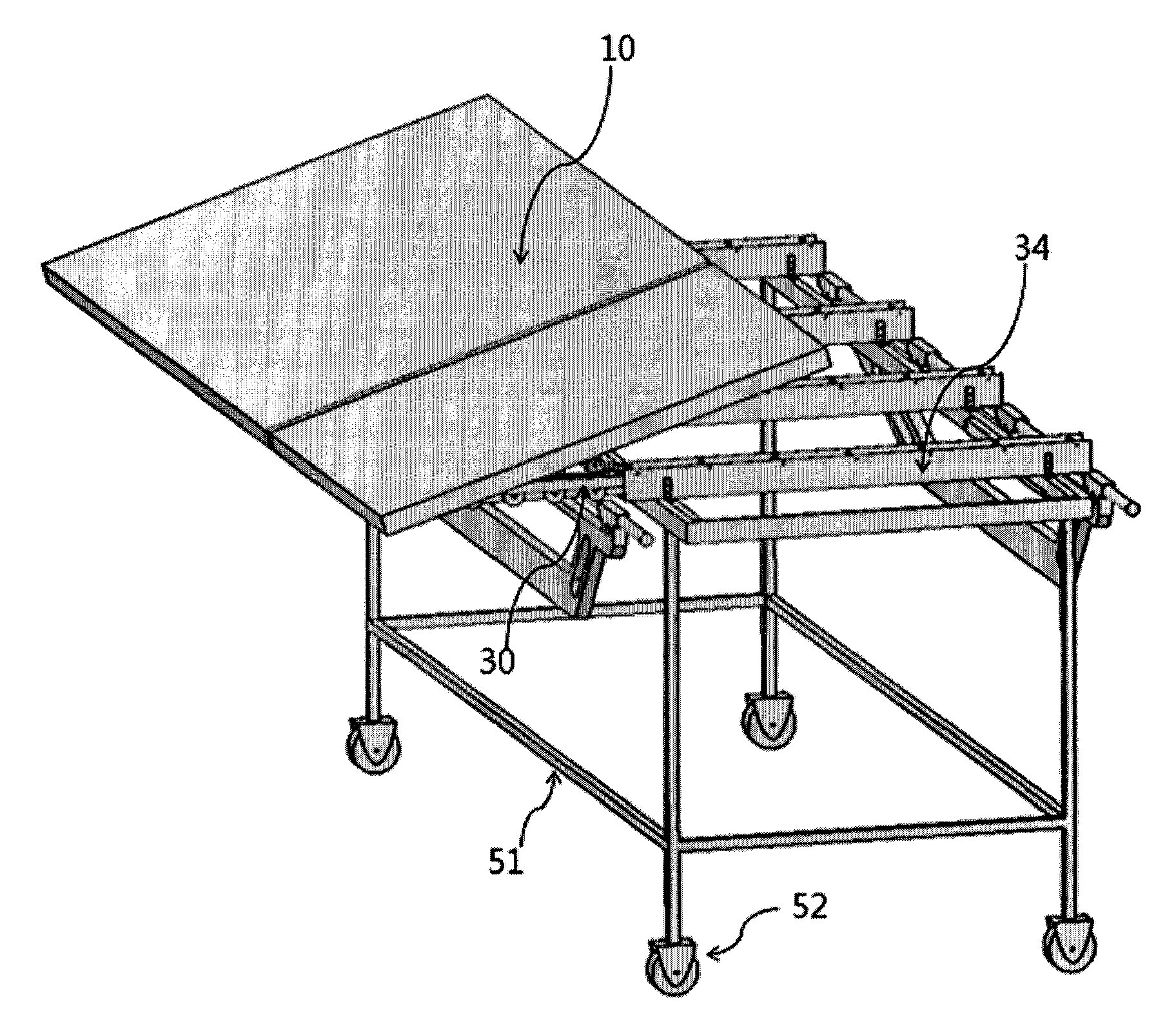
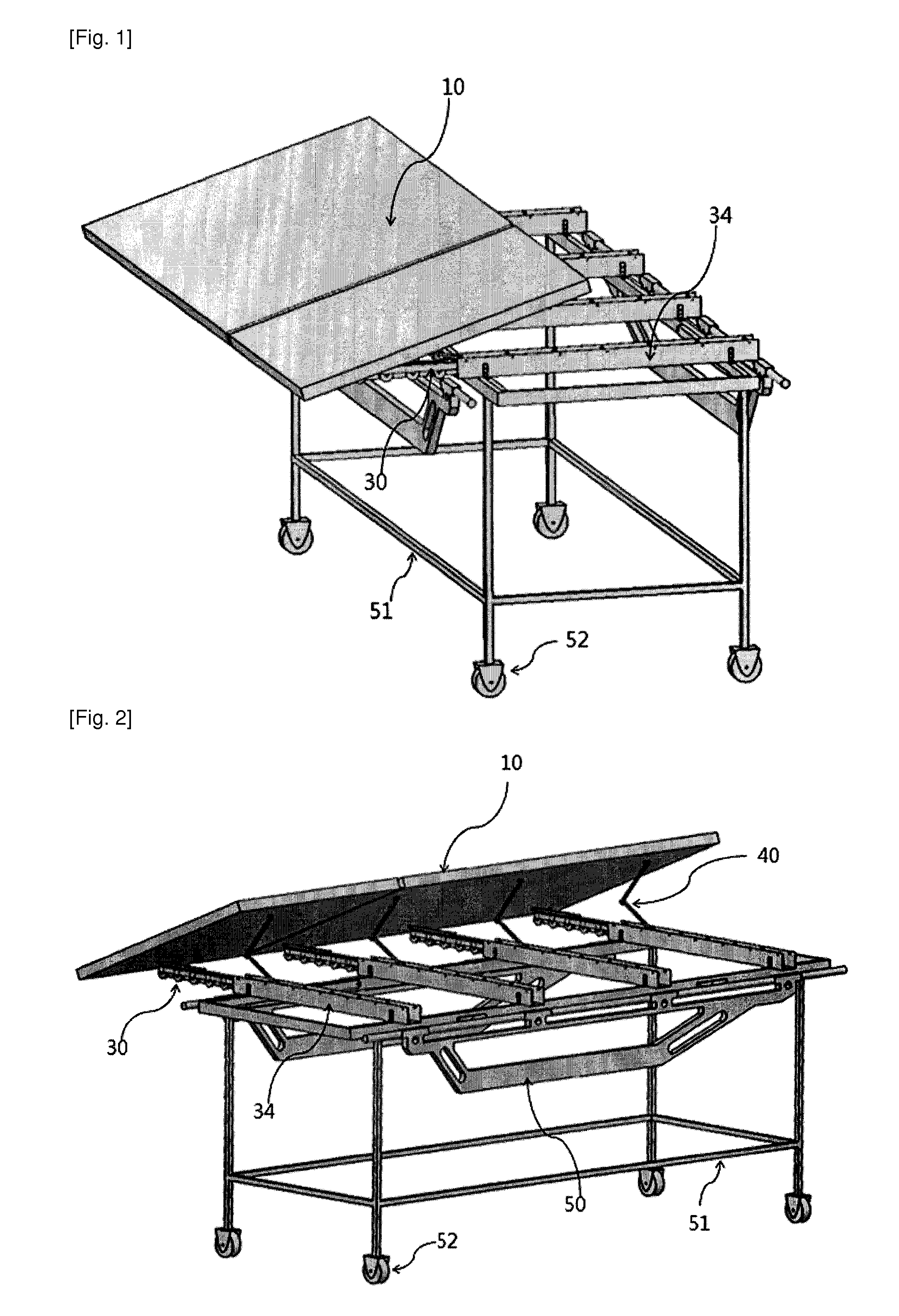
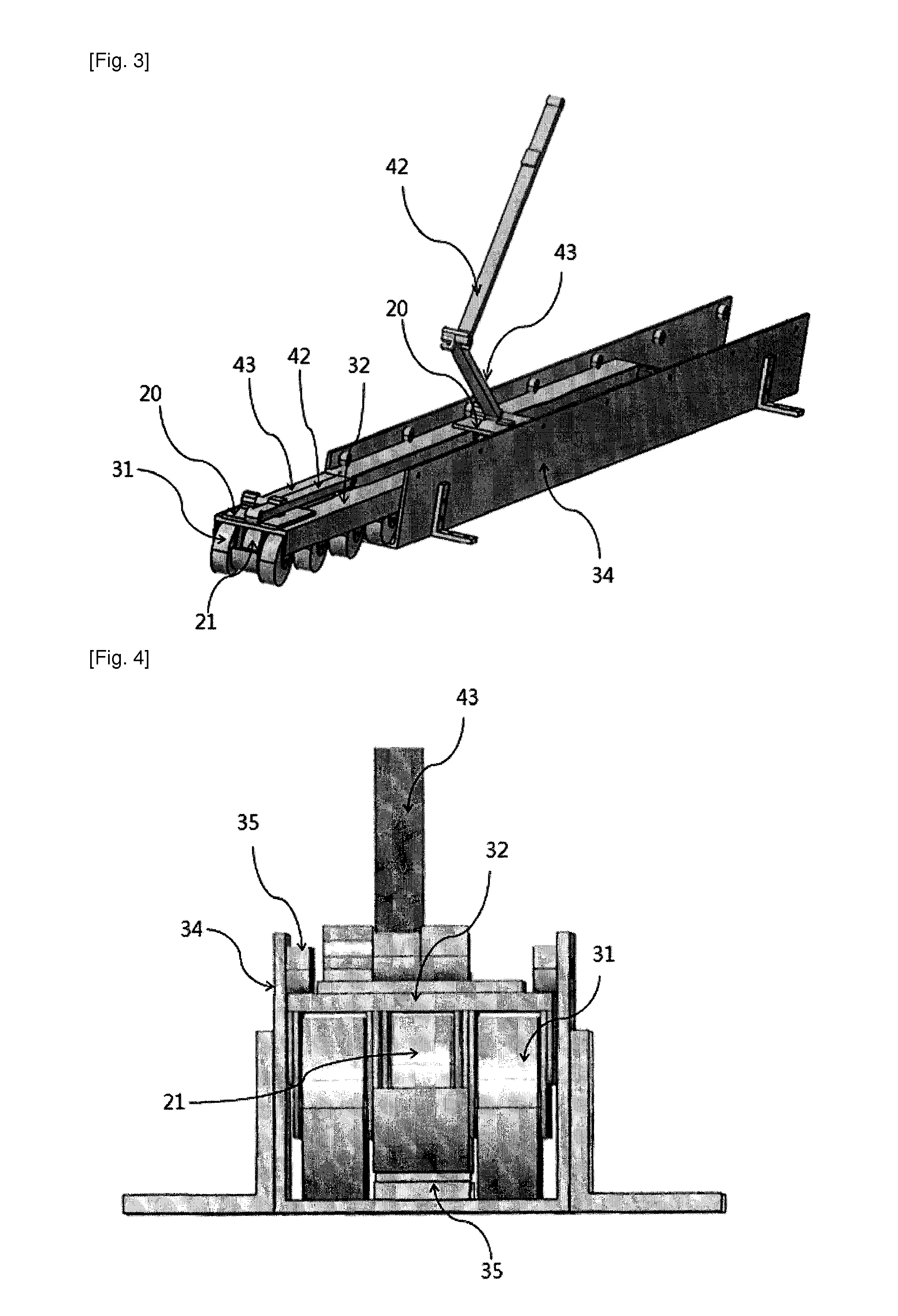
[0023]As shown in FIGS. 1 and 2, a transfer arm 30 with rollers is installed beneath a top movable board in order to easily load a top movable board 10 of a patient movable bed onto a patient bed during a transfer of a patient. The top movable board 10 is not directly connected with a transfer arm 30, but is directly connected in such a manner that a wheeled chassis 20 of FIG. 3 is directly connected to the top movable board 10 via a linkage 40 in order for the top movable board 10 to easily move along the transfer arm 30. As shown in FIGS. 4, 5 and 7, the wheeled chassis 20 is equipped with the rollers 21, so when the top movable board 10 moves, the wheeled chassis 20 fixed at the top movable board 10 move along the transfer arm 30 via a wheeled chassis guide grove 37 with the aid of the linkages 41 to 44, and 46 to 48 of FIG. 7.

[0024]When the wheeled chassis 20 moves along with the top movable board 10, and the wheeled chassis 20 are caught by the end portion 33 of the transfer ar...


PUM


Abstract

A patient transfer apparatus of the present invention is configured in that a top movable board of a patient movable bed is easily movable onto a patient bed mattress by using a transfer arm and a wheeled chassis moving on the transfer arm, so as to cause minimum inconveniences to a patient and allow for a transfer with ease when the patient who is not able to move freely is transferred between the patient bed and the patient movable bed. In addition, a linkage device is installed beneath the top movable board to easily incline the top movable board toward the body of the patient. Therefore, the patient can be taken onto or removed from the patient movable bed merely by lying on his/her side from the posture of lying on his/her back, thereby minimizing inconvenience to the patient caused by a patient transfer, and enabling the patient transfer to be easily performed with a smaller number of people. Further, the patient transfer apparatus of the present invention eliminates the necessity of external power source for patient transfer, and has the advantages of a simple configuration and reduced cost.

Description

TECHNICAL FIELD[0001]The present invention relates to a patient transfer apparatus generally used for a patient transfer between a patient bed and a patient movable bed or a patient transfer between a patient movable bed and various medical diagnosis apparatuses, by which it is possible to easily transfer a patient without causing inconveniences to the patient when transferring a patient, who is very weak to move for himself, between a patient bed and a patient movable bed.BACKGROUND ART[0002]Lots of patient transfer apparatus are being filed and are already registered as patents in advanced countries including the USA whereas less patents are disclosed in Korea. The inventions in foreign countries which are being filed or are already registered as patents are formed of complicated parts and are very hard to use, as a result of which actual applications are very limited. For example, the apparatuses of U.S. Pat. No. 7,000,268, U.S. Pat. No. 5,937,456, U.S. Pat. No. 4,873,732, U.S. P...

Claims


Application Information

Patent Timeline
IPC IPC(8): A61G7/10
CPCA61G7/103A61G7/1046A61G7/1036A61G7/08A61G7/05
Inventor JEI, YANGGYU
Owner JEI YANGGYU
Why Eureka
Try Eureka