
Maximized Thermal Efficiency Engines

a technology of thermal efficiency and maximum efficiency, applied in the direction of machines/engines, ericsson type engines, hot gas positive displacement engine plants, etc., can solve the problems of inability to separate hot and cold cylinders, and inability to achieve high thermal efficiency. achieve the effect of being usabl

Inactive Publication Date: 2012-03-22
PINTO ADOLF PATRICK
View PDF6 Cites 2 Cited by
  • Summary
  • Abstract
  • Description
  • Claims
  • Application Information

AI Technical Summary

Benefits of technology

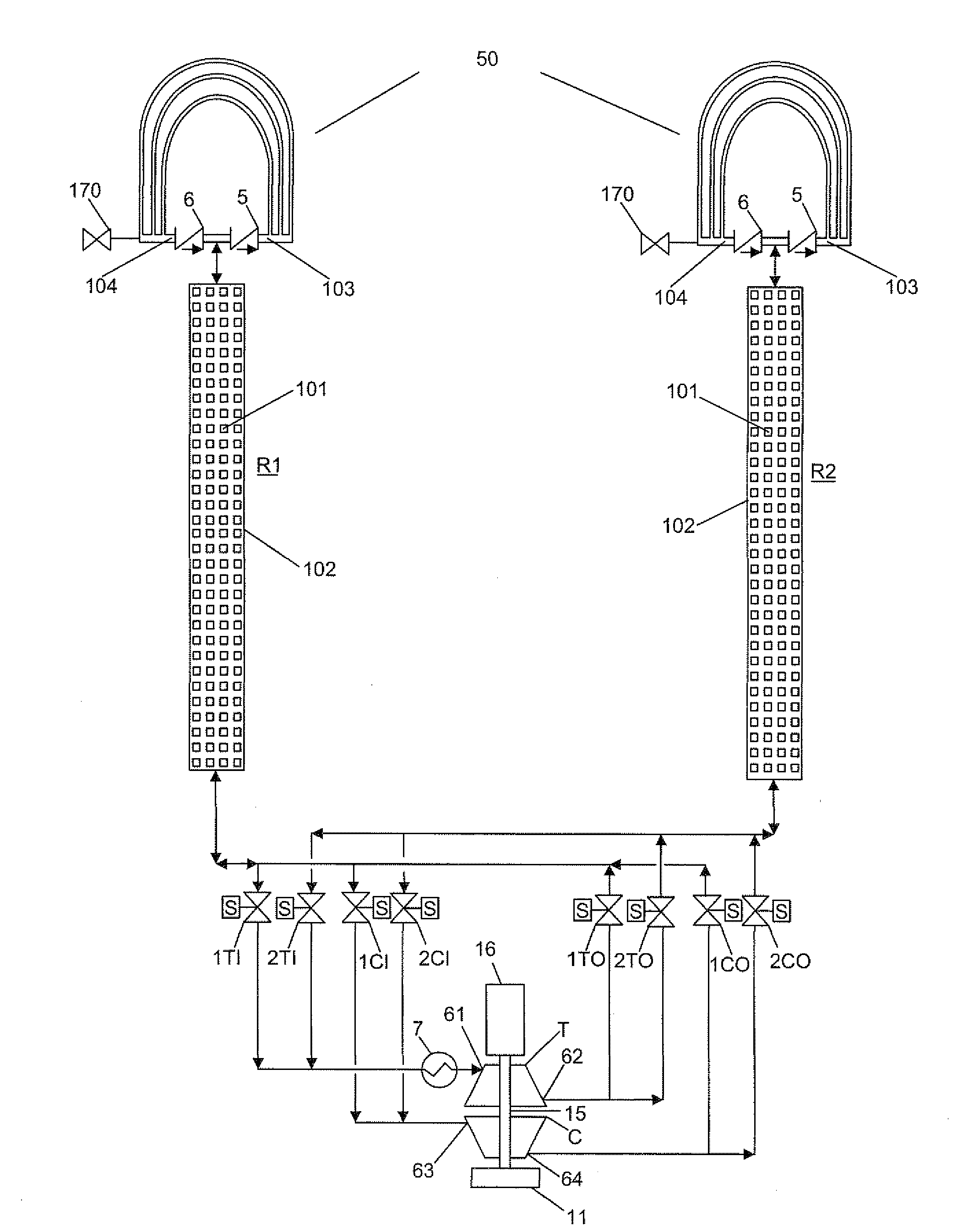
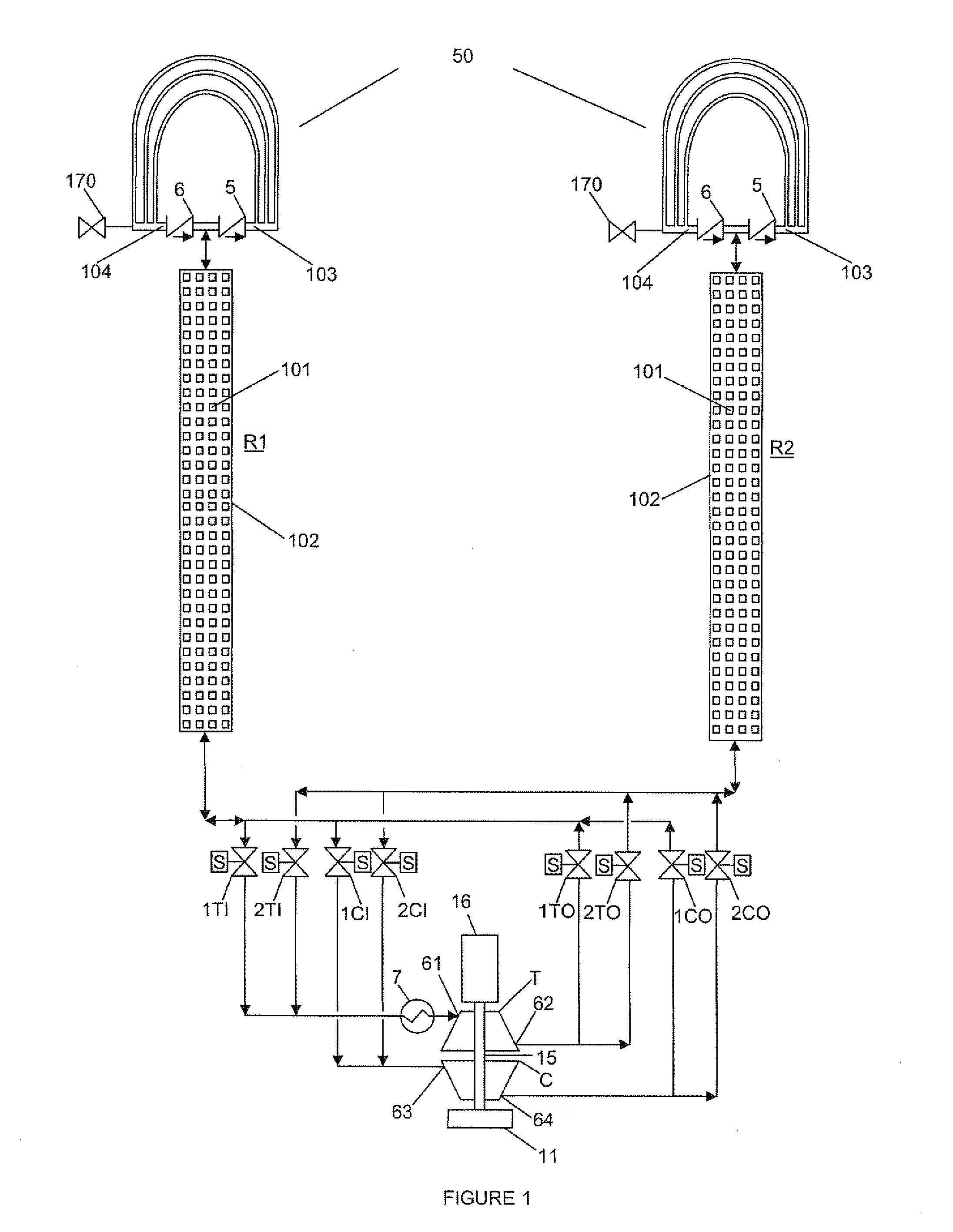
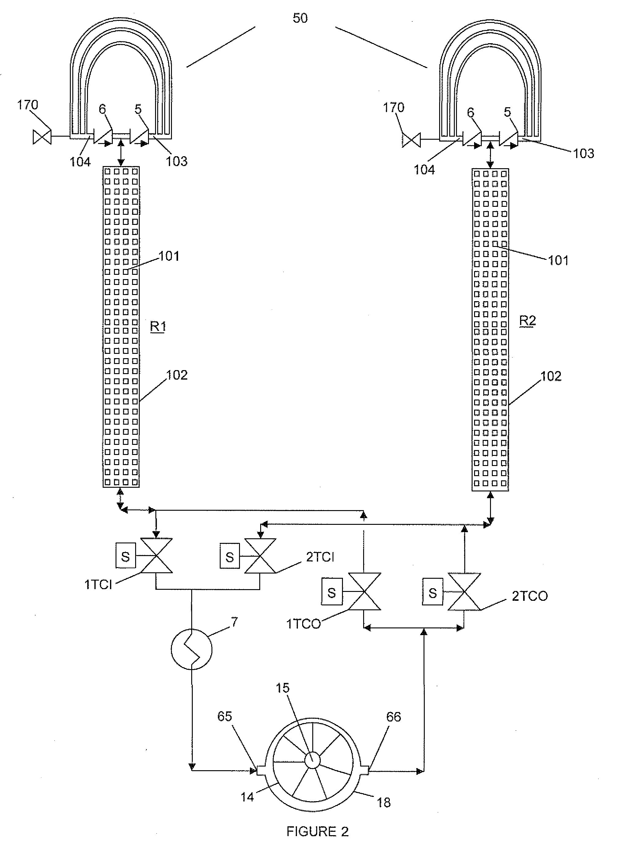
[0004]Two basic types of engines are possible based on the proposed engine model. The first basic type of engine consists of paired heat regenerators positioned on either side of the heat addition and pressure variation means, and are part of engines that operate 180° out of phase with each other. In this first basic design type, the heat regenerators may be considered as large pressure vessels, where the pressure in each heat regenerator varies cyclically, and inversely with respect to the pressure in its paired heat regenerator, from a maximum pressure PMAX to a minimum pressure PMIN, as the working gas flows back and forth from one heat regenerator to the other through the heat addition and pressure variation means. Therefore, in the first basic design type of engine, the heat regenerators of each pair share the heat addition means, the pressure variation means, and portions of the working gas. The second basic design type of engine consists of a single heat regenerator. During each expansion step in engines of the second basic design type, the expanding working gas flows out of the second end of the heat regenerator, has heat added to it by the heat addition means, and interacts with and transfers to the pressure variation means the readily usable energy generated by the expansion of the working gas. The pressure variation means then utilizes a portion of the readily usable energy generated in the previous expansion step to push the working gas back into the heat regenerator through its second end to cause each subsequent compression step to occur.

Problems solved by technology

Separate hot and cold cylinders increase cost.
However, the hot gas engines developed so far have not succeeded in achieving the high thermal efficiency that is potentially possible.
The inability to achieve high thermal efficiency is primarily because existing state of the art hot gas engines do not have their heat regenerators and their working gas processing steps designed for optimum heat regeneration.
U.S. Pat. No. 4,455,825 pointed out that the working gas processing steps, and consequently the heat regeneration were not optimum.
The heat regeneration was not optimum because working gas flowed between the hot and cold cylinders during the expansion and compression steps.
Working gas that is present in, or that flows into the cold cylinder during the expansion step, and the working gas that is present in or flows into the hot cylinder during the compression step, produce negative work loops, and negatively impact the thermal efficiency.
However, the engines in those patents did not address the role and design of the heat regenerator, and the engines in those patents continued to use separate hot and cold cylinders.

Method used


Image

  • Maximized Thermal Efficiency Engines
  • Maximized Thermal Efficiency Engines
  • Maximized Thermal Efficiency Engines

Examples


Embodiment Construction

[0014]First heat regenerator (R1) and second heat regenerator (R2) in FIGS. 1, 2, and 3, and heat regenerator (R) in FIGS. 4 and 5 comprise thermal capacity possessing, finely divided, heat regenerator material (101), enclosed in a pressure confining, heat insulating, minimized heat conducting boundary (102) having a first end and a second end. Fluid seal connected to the first end of each heat regenerator (R1, R2, and R) is heat rejection means (50). The heat rejection means (50) is provided with inlet and outlet ports (103) and (104) respectively. Two one way check valves (5) and (6) are provided in the flow paths from the heat regenerator (R1, R2 and R) to the heat rejection means (50). Check valve (5) ensures that when the working gas flows from the heat regenerator to the heat rejection means it will only enter through the inlet port (103), and check valve (6) ensures that when the working gas flows from the heat rejection means to the heat regenerator it will only flow through...


PUM


Abstract

This disclosure provides a method for efficiently converting heat energy to readily usable energy with maximized thermal efficiency. Maximized thermal efficiency is obtained by the use of heat regeneration and working gas processing steps that optimize the heat regeneration, so that any heat that is supplied to the working gas from the external heat sourse is supplied at the maximum temperature, and any heat that is rejected from the working gas to an external heat sinks is rejected at the minimum temperature, given the constraints of the the heat source and heat sink temperatures. Two basic designs of engines are proposed. One of the basic designs uses pairs of heat regenerators, and would be suitable for stationary power generation applications. The other basic design uses single heat regenerators and would be suited for motive power applications. Both piston cylinder and turbocompressor driven engine applications can be used in each of the two basic designs of engines.

Description

FIELD OF THE DISCLOSURE[0001]This disclosure relates to hot gas engines, particularly to piston cylinder engines and gas turbine engines capable of having improved thermal efficiency, and more particularly to hot gas engines of the Stirling type.BACKGROUND OF THE DISCLOSURE[0002]Hot gas engines of the Stirling type have been primarily external combustion engines employing pistons and cylinders. State of the art hot gas engines with pistons that are configured to turn drive shafts are designed with hot and cold cylinders, and a heat regenerator connected between the hot and cold cylinders. Separate hot and cold cylinders increase cost. Extensive developmental work has been carried out on hot gas engines because of their promise of high thermal efficiency. However, the hot gas engines developed so far have not succeeded in achieving the high thermal efficiency that is potentially possible. The inability to achieve high thermal efficiency is primarily because existing state of the art ...

Claims


Application Information

Patent Timeline
Patent Type & Authority Applications(United States)
IPC IPC(8): F02G1/043
CPCF02G2242/00F02G1/043
Inventor PINTO, ADOLF P.
Owner PINTO ADOLF PATRICK
Learn More