Method and apparatus for forming a can shell

a technology of can shells and can shells, which is applied in the field of methods and apparatus for forming can shells, can solve the problems of difficult to produce an adjustable and precisely controllable axial force on the inner pressure sleeve, and none of the patents provide all of the above desirable features, and achieve uniform and precise can shells. high speed, the effect of high speed

Active Publication Date: 2012-03-22
CONTAINER DEVELOPMENT LTD
View PDF7 Cites 19 Cited by
  • Summary
  • Abstract
  • Description
  • Claims
  • Application Information

AI Technical Summary

Benefits of technology

[0005]The present invention is directed to improved method and apparatus or tooling for high speed production of can shells and which provide all of the desirable features mentioned above. The tooling assembly of the invention is also ideally suited for producing a can shell such as disclosed in applicant's U.S. Pat. No. 7,341,163 and in applicant's published patent application No. US-2005-0

Problems solved by technology

The high speed axial reciprocating movement of the pins and the single piston which actuates the pins create undesirable additional heat, and is difficult to produce an adjustable and precisely control

Method used


Image

  • Method and apparatus for forming a can shell
  • Method and apparatus for forming a can shell
  • Method and apparatus for forming a can shell

Examples


Embodiment Construction

[0012]Referring to FIG. 11, a greatly enlarged shell 15 is formed from sheet metal or aluminum having a thickness of about 0.0082 inch. The shell 15 includes a flat circular center panel 16 which is connected by a frusto-conical or inclined annular panel wall portion 17 and a substantially cylindrical panel wall portion 18 to an annular countersink 19 having an inclined or frusto-conical inner wall portion 21 and a generally U-shaped cross-sectional configuration. The countersink 19 also has a slightly inclined annular outer wall portion 22 connected to an annular inclined lower chuckwall portion 23 which is connected to an upwardly curved upper chuckwall portion 24 by a slight angular break 25. The curved upper wall portion 24 of the chuckwall connects with an inclined or frusto-conical annular inner wall portion 26 of a crown portion 28 having a downwardly curved outer peripheral lip portion 29. The cross-sectional configuration or profile of the shell 15 is more specifically disc...


PUM

PropertyMeasurementUnit
Pressureaaaaaaaaaa
Radiusaaaaaaaaaa

Abstract

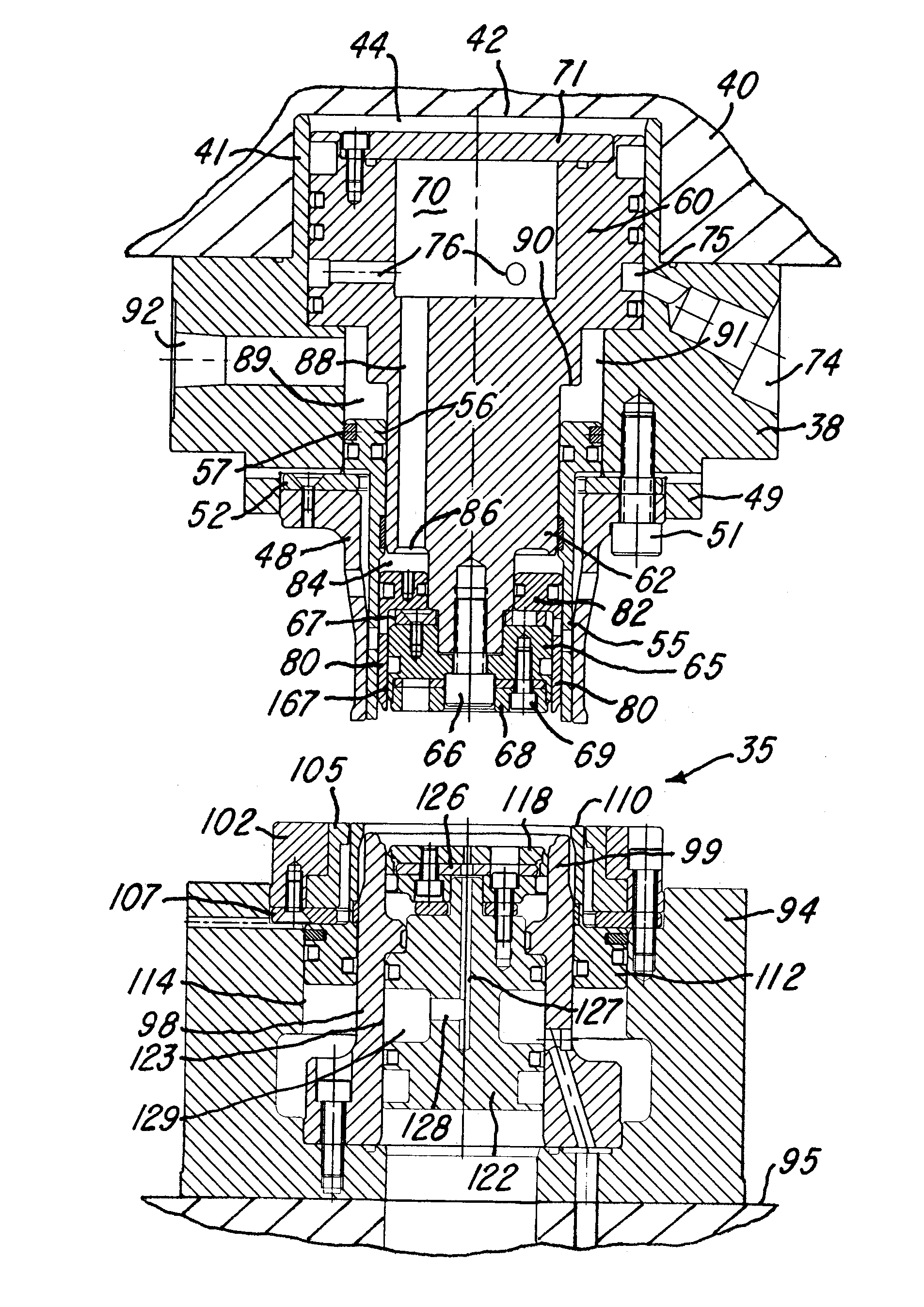
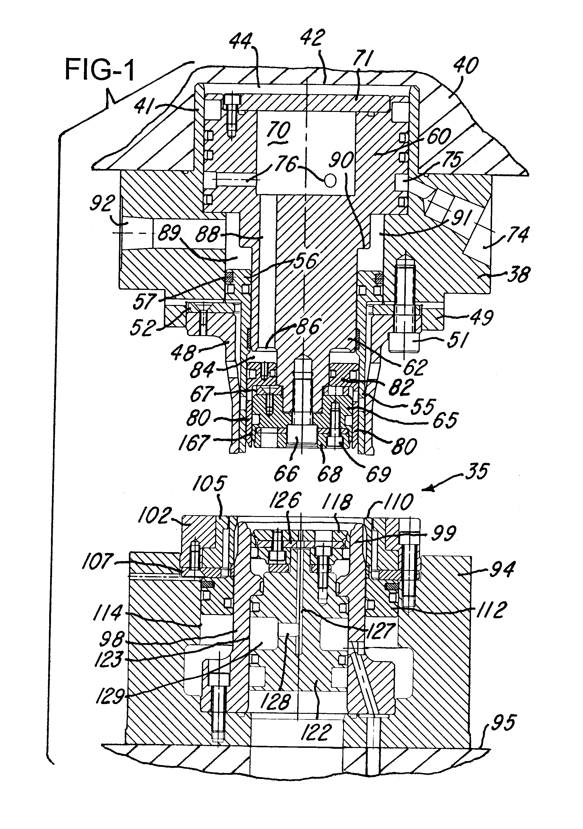
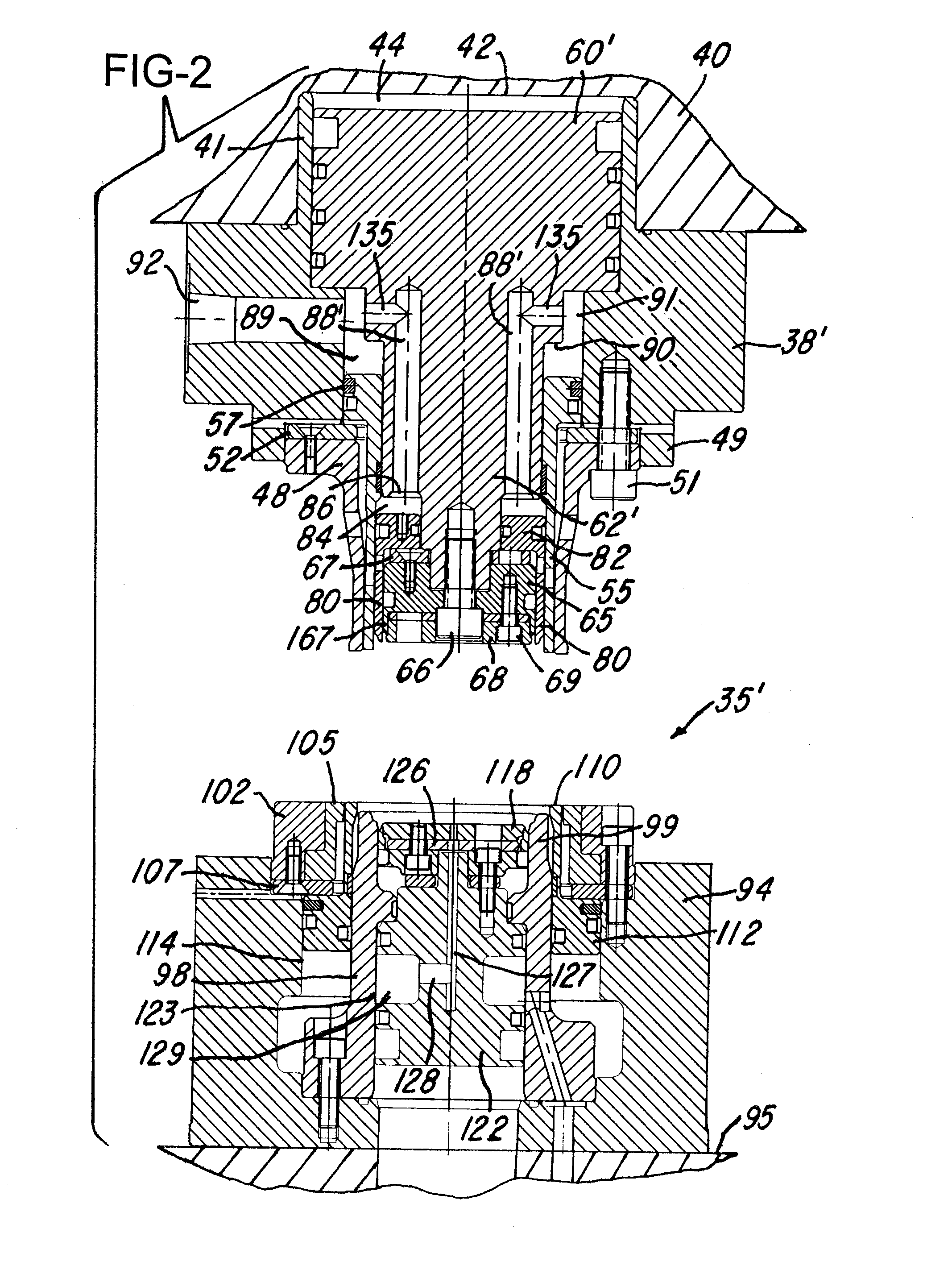
Can shells are produced with tooling installed on a mechanical press, and the tooling includes an upper retainer supporting a blank and draw die enclosing an outer pressure sleeve and an inner pressure sleeve surrounding a die center punch, all having pistons. An air chamber is connected by air spring passages to the inner pressure sleeve piston, and the outer pressure sleeve receives the same air as the air chamber or lower pressure air. The die center punch has an insert which initiates the drawing of a cup, and the inner pressure sleeve and die center punch have contoured surfaces which mate with opposing surfaces on a die core ring to form and clamp the chuckwall of the shell during downstroke of the press. A panel punch has peripheral surfaces which form the panel wall and countersink of the shell during upstroke of the press.

Description

BACKGROUND OF THE INVENTION[0001]This invention relates to the method and apparatus for forming a can shell from sheet metal or sheet aluminum, for example, such as the methods and apparatus or tooling disclosed in U.S. Pat. No. 4,713,958, U.S. Pat. No. 4,716,755, U.S. Pat. No. 4,808,052, U.S. Pat. No. 4,955,223, U.S. Pat. No. 6,658,911 and U.S. Pat. No. 7,302,822. The disclosures of these patents are herein incorporated by reference to supplement the detail description of the present invention.[0002]In such tooling assembly or apparatus, it has been found desirable for the apparatus to be constructed for use in a single action mechanical press such as disclosed in above mentioned U.S. Pat. No. 4,955,223 and U.S. Pat. No. 7,302,822 and also for use in a double action mechanical press, for example, as disclosed in above-mentioned U.S. Pat. No. 4,716,755 and U.S. Pat. No. 6,658,911. A single action high speed press is simpler and more economical in construction and is more economical ...

Claims


Application Information

Patent Timeline
IPC IPC(8): B21D22/21
CPCB21D51/44B21D22/24B21D22/20B21D24/04B21D24/12B21D51/26
Inventor STODD, R. PETER
Owner CONTAINER DEVELOPMENT LTD
Why Eureka
Try Eureka