Ultrasonic testing apparatus for pipe or tube end portion

Active Publication Date: 2012-03-22
NIPPON STEEL CORP
View PDF7 Cites 5 Cited by
  • Summary
  • Abstract
  • Description
  • Claims
  • Application Information

AI Technical Summary

Benefits of technology

[0016]According to the above-described preferable configuration, since the coupling medium is supplied in the tangential direction of a predetermined arc around the vertical center axis through the coupling medium supply port, an eddy current of the coupling medium is produced in the coupling medium reserver part body. By this eddy current, a contamination (for example, for a steel pipe or tube, droppings of scale adhering to the steel pipe or tube surface) that may be contained in the coupling medium is carried to the coupling medium discharge port and is discharged to the outside. Therefore, the coupling medium reserver part

Problems solved by technology

In the configuration shown in FIG. 1, unfortunately, the pipe P is supported at least at two points outside the water tank T. The problem, therefore, is that ultrasonic testing cannot be performed on a pipe end portion, where such a two-point support cannot be used, within the water W in the water tank T. Therefore, the configuration shown in FIG. 1 is mainly used in ult

Method used


Image

  • Ultrasonic testing apparatus for pipe or tube end portion
  • Ultrasonic testing apparatus for pipe or tube end portion
  • Ultrasonic testing apparatus for pipe or tube end portion

Examples


Embodiment Construction

[0023]One embodiment of the present invention will now be described with reference to the accompanying drawings.

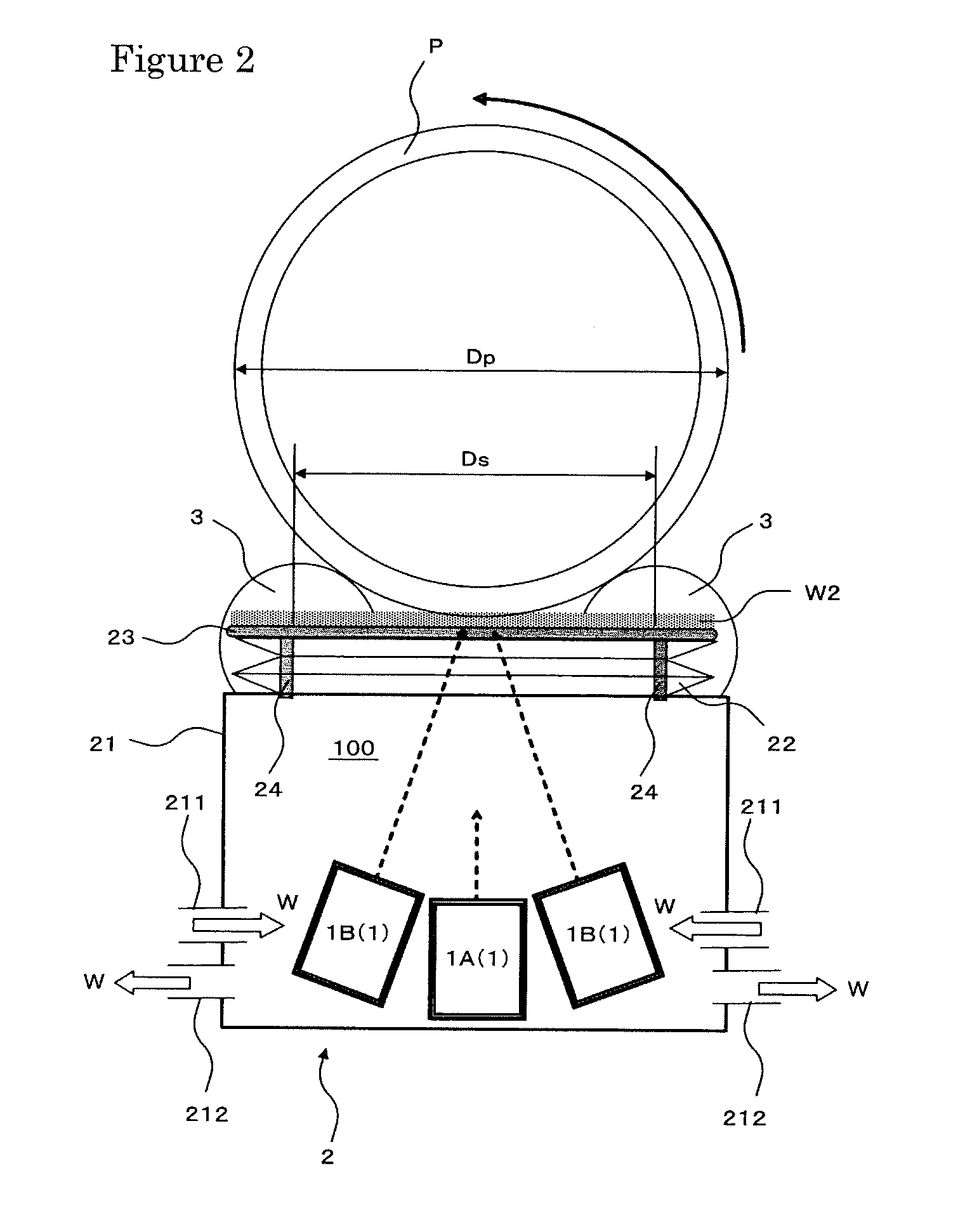
[0024]FIG. 2 is a sectional view, as viewed from the front, of an ultrasonic testing apparatus in accordance with one embodiment of the present invention. FIG. 3 is a plan view of the ultrasonic testing apparatus shown in FIG. 2.

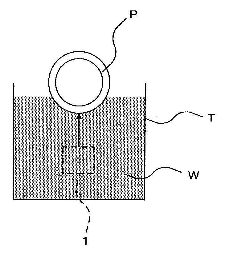
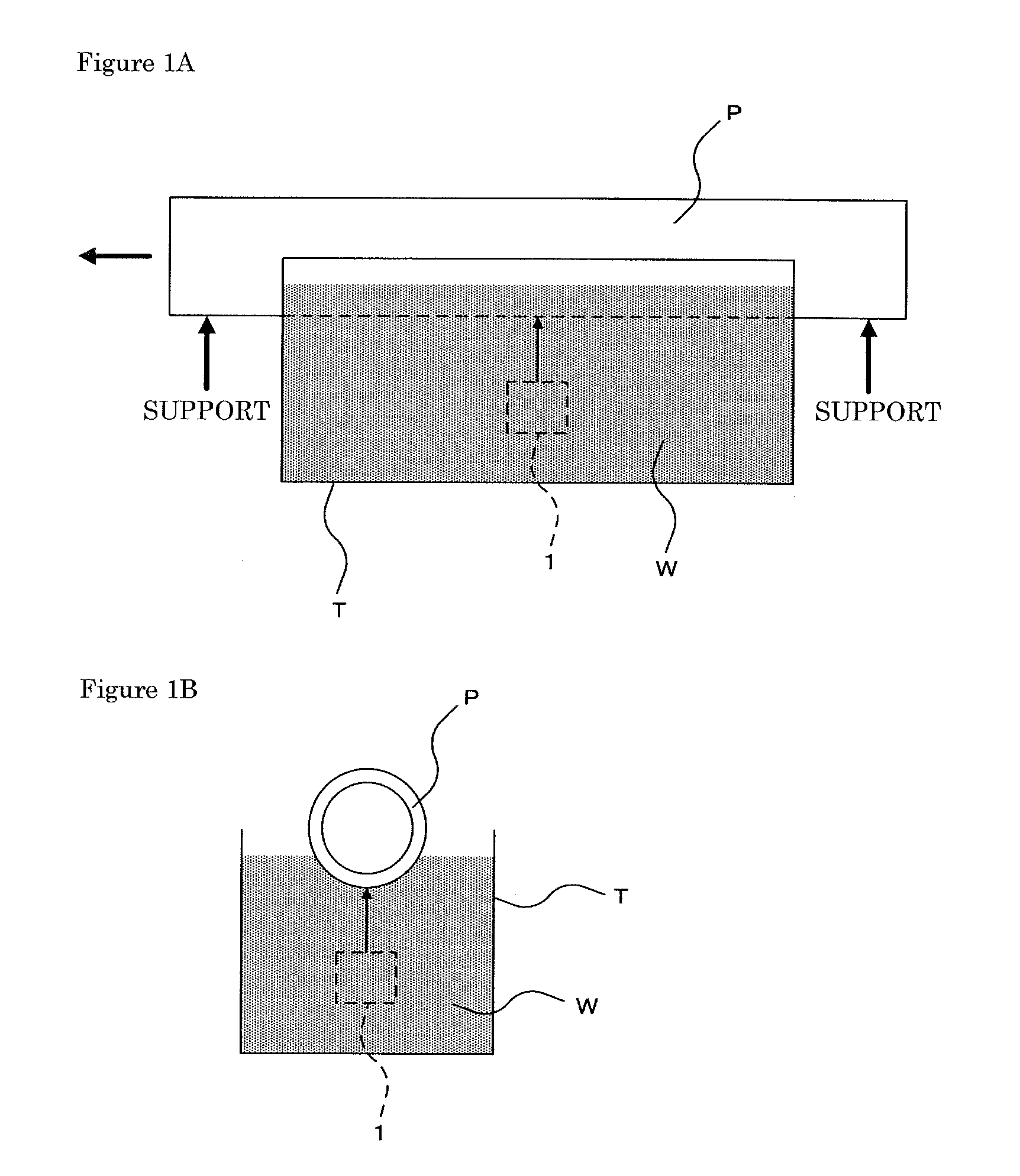
[0025]As shown in FIG. 2 or FIG. 3, the ultrasonic testing apparatus 100 of this embodiment comprises an ultrasonic probe 1 which is disposed under the end portion of a pipe P laid in the horizontal direction to face the pipe P end portion, the ultrasonic probe 1 transmitting ultrasonic waves to the end portion of the pipe P and receiving the ultrasonic waves therefrom; and a probe holder 2 housing the ultrasonic probe 1 which is disposed under the end portion of the pipe P to face the pipe P end portion and follows the pipe P rotating in the circumferential direction.

[0026]The pipe P is placed on turning rollers 3, so that the pipe P is rotated in...


PUM


Abstract

An ultrasonic testing apparatus for a pipe end portion, which enables accurate ultrasonic testing, comprises an ultrasonic probe disposed under the pipe end portion. The probe 1 transmits ultrasonic waves to the pipe end portion and receives the ultrasonic waves therefrom. A probe holder houses the probe which is disposed under the pipe end portion to face the pipe end portion and follows the pipe rotation. The probe holder comprises a coupling medium reserver part that surrounds a space between the probe and the pipe end portion to contain a coupling medium therein and comprises a coupling medium reserver part body into which the coupling medium is supplied. An annular bellows part, which communicates with the reserver part body, can expand and contract vertically and an annular spacer, which is attached to the upper side of the bellows part and an upper surface thereof has a flat horizontal surface.

Description

TECHNICAL FIELD[0001]The present invention relates to an apparatus for ultrasonic testing of an end portion of a pipe or tube such as a steel pipe or tube. More particularly, the present invention relates to an ultrasonic testing apparatus for a pipe or tube end portion, which enables accurate ultrasonic testing by the stable interposition of a coupling medium between the pipe or tube (hereinafter referred to as “pipe” when deemed appropriate) end portion and an ultrasonic probe.BACKGROUND ART[0002]An ultrasonic testing method has been employed widely as a nondestructive inspection method for a pipe such as a steel pipe. In the ultrasonic testing method, a coupling medium such as water is interposed between the pipe and an ultrasonic probe, ultrasonic waves transmitted from the ultrasonic probe are applied to the pipe, and the ultrasonic waves reflected by the pipe are received by the ultrasonic probe.[0003]As an ultrasonic testing method in which ultrasonic probe is disposed under ...

Claims


Application Information

Patent Timeline
IPC IPC(8): G01N29/04
CPCG01N29/225G01N29/27G01N2291/2634G01N2291/103G01N29/28G01N29/275G01N2291/052G01N2291/056
Inventor FUJIWARA, KENJIKUBOTA, HIROSHIOBATA, TOMOYUKIYAMANO, MASAKI
Owner NIPPON STEEL CORP
Why Eureka
Try Eureka