Supercharge Your Innovation With Domain-Expert AI Agents!

Printed circuit board with vibration-generating electronic component

Active Publication Date: 2012-03-22
ABL IP HLDG
View PDF2 Cites 2 Cited by
  • Summary
  • Abstract
  • Description
  • Claims
  • Application Information

AI Technical Summary

Benefits of technology

[0008]In a preferred embodiment, at least one of the slots runs parallel to a side wall of the electronic component. Express reference is made to the fact that this feature does not require the side wall of the electronic component to be in a straight line. If the side wall is curved, the slot is curved parallel thereto. The feature “parallel” merely includes that the respectively shortest connecting line between the side wall and the slot is in each case perpendicular to the tangent at the contour of the side wall or of the slot. The preferred embodiment that a slot runs parallel to the side wall of the electronic component is especially advantageous in particular when the electronic component is connected in the region of the side wall, i.e. with one end, to the conductor tracks. By means of the electrical connection of the electronic component to the conductor tracks, which results along with a mechanical connection, mechanical coupling-in of the oscillations generally takes place. If the slot runs parallel to the side wall of the electronic component, the slot is arranged in such a way that in each case approximately the same phase of the oscillation which is triggered by the electronic component passes to the slot, that is over the entire length. As a result, the oscillation is suppressed particularly efficiently.

Problems solved by technology

Even if the oscillation of the ceramic capacitor has only a very low amplitude under the piezoelectric effect, considerable oscillations in the printed circuit board may result since the forces acting are very great.
The oscillating printed circuit board generates sound and therefore undesirable perceptible noise.
Owing to the need for the provision of electrical contacts, said contacts cannot always be effectively decoupled, however.

Method used


Image

  • Printed circuit board with vibration-generating electronic component
  • Printed circuit board with vibration-generating electronic component

Examples


Embodiment Construction

[0005]The object of the invention is to develop a printed circuit board of the type mentioned at the outset in such a way that sound is effectively suppressed.

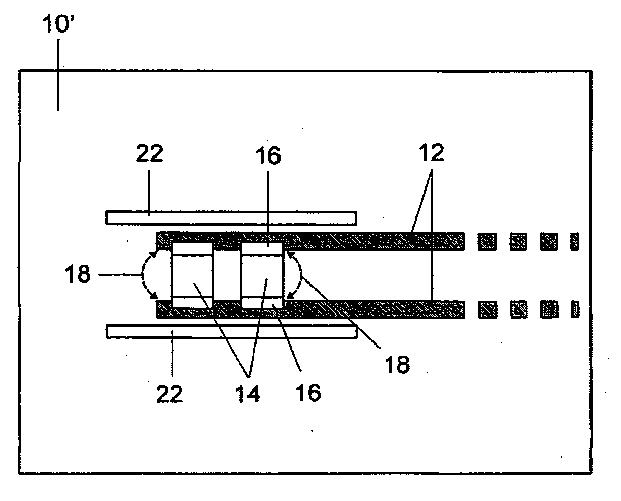
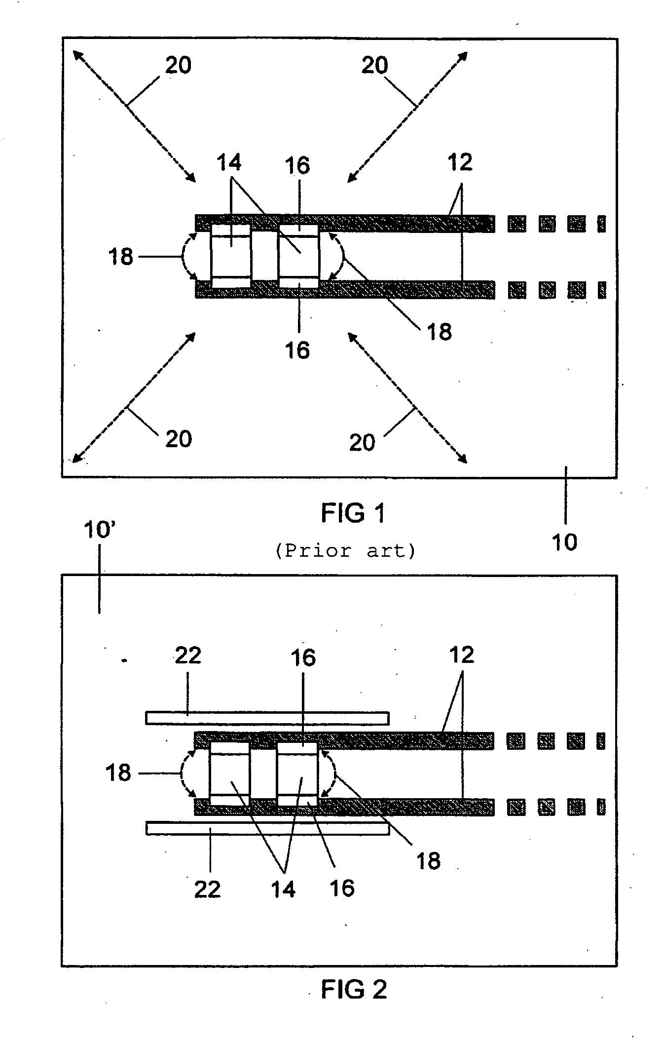
[0006]According to the invention, at least one slot is provided in the printed circuit board. The slot is used for preventing the propagation of oscillations triggered by the electronic component over the printed circuit board. This can be understood such that the electronic component can initially trigger oscillations in its direct region of influence, but these oscillations only propagate as far as the slot on the side of the slot on which the electronic component is arranged and not beyond the slot, i.e. on the side of the slot on which the electronic component is not arranged. Since a printed circuit board generally has a flat surface on which the (copper) conductor tracks are formed, the slot produces an interruption in the flat surface, with the result that surface waves and transverse oscillations of the printed circuit...


PUM


Abstract

Surface mounted ceramic capacitors (14) on printed circuit boards (10′) are subject to vibrations (18) caused by the piezo effect. Other electronic components are subject to magnetostriction and likewise generate vibrations. In prior art, the vibrations can propagate (20) on a printed circuit board (10). To suppress the propagation of the vibrations caused by the electronic component (14), the invention provides at least one slot (22) in the printed circuit board (10′). The slot (22) extends, for example, parallel to a side wall of the electronic component (14).

Description

TECHNICAL FIELD[0001]The invention relates to a printed circuit board, on which at least two conductor tracks are arranged, to which an electronic component is connected which triggers oscillations during operation.PRIOR ART[0002]It is known that a printed circuit board is a relatively thin, flat plate which is usually made from plastic. The conductor tracks are generally produced from copper, the copper typically being applied electrochemically to the printed circuit board. “Operation” of the electronic component is understood to mean that the electronic component has current flowing through it or that at least a feed voltage is present.[0003]One example of an electronic component which triggers oscillations during operation is a ceramic capacitor. Since the ceramic capacitor is mounted on the printed circuit board, it is also referred to as a surface-mounted ceramic capacitor (SMD ceramic capacitor, surface mounted device). Ceramic capacitors demonstrate a piezoelectric effect. Th...

Claims


Application Information

Patent Timeline
IPC IPC(8): H05K1/16
CPCH05K1/0231H05K1/0271H05K2201/09036H05K2201/2045H05K2201/1003H05K2201/10636H05K2201/09063Y02P70/50H05K1/02H05K1/18
Inventor SCHALLMOSER, OSKAR
Owner ABL IP HLDG
Features
  • R&D
  • Intellectual Property
  • Life Sciences
  • Materials
  • Tech Scout
  • Unparalleled Data Quality
  • Higher Quality Content
  • 60% Fewer Hallucinations
Learn More