Target assembly

a technology of target and assembly, applied in the direction of electrolysis components, vacuum evaporation coatings, coatings, etc., can solve the problem of low target utilization ra

Inactive Publication Date: 2012-03-22
HONG FU JIN PRECISION IND (SHENZHEN) CO LTD +1
View PDF5 Cites 0 Cited by
  • Summary
  • Abstract
  • Description
  • Claims
  • Application Information

AI Technical Summary

Benefits of technology

[0004]Magnetron sputtering is a process whereby atoms are ejected from a solid target due to a bombardment of the target by energetic particles of a magnetron. It is commonly used for thin-film deposition, etching and analytical techniques. Typically, the position between the target and the magnetron cannot be adjusted so the bombarded area of the target cannot be adjusted, and the utilization rate of the target is low.

Problems solved by technology

Typically, the position between the target and the magnetron cannot be adjusted so the bombarded area of the target cannot be adjusted, and the utilization rate of the target is low.

Method used


Image

  • Target assembly
  • Target assembly
  • Target assembly

Examples


Embodiment Construction

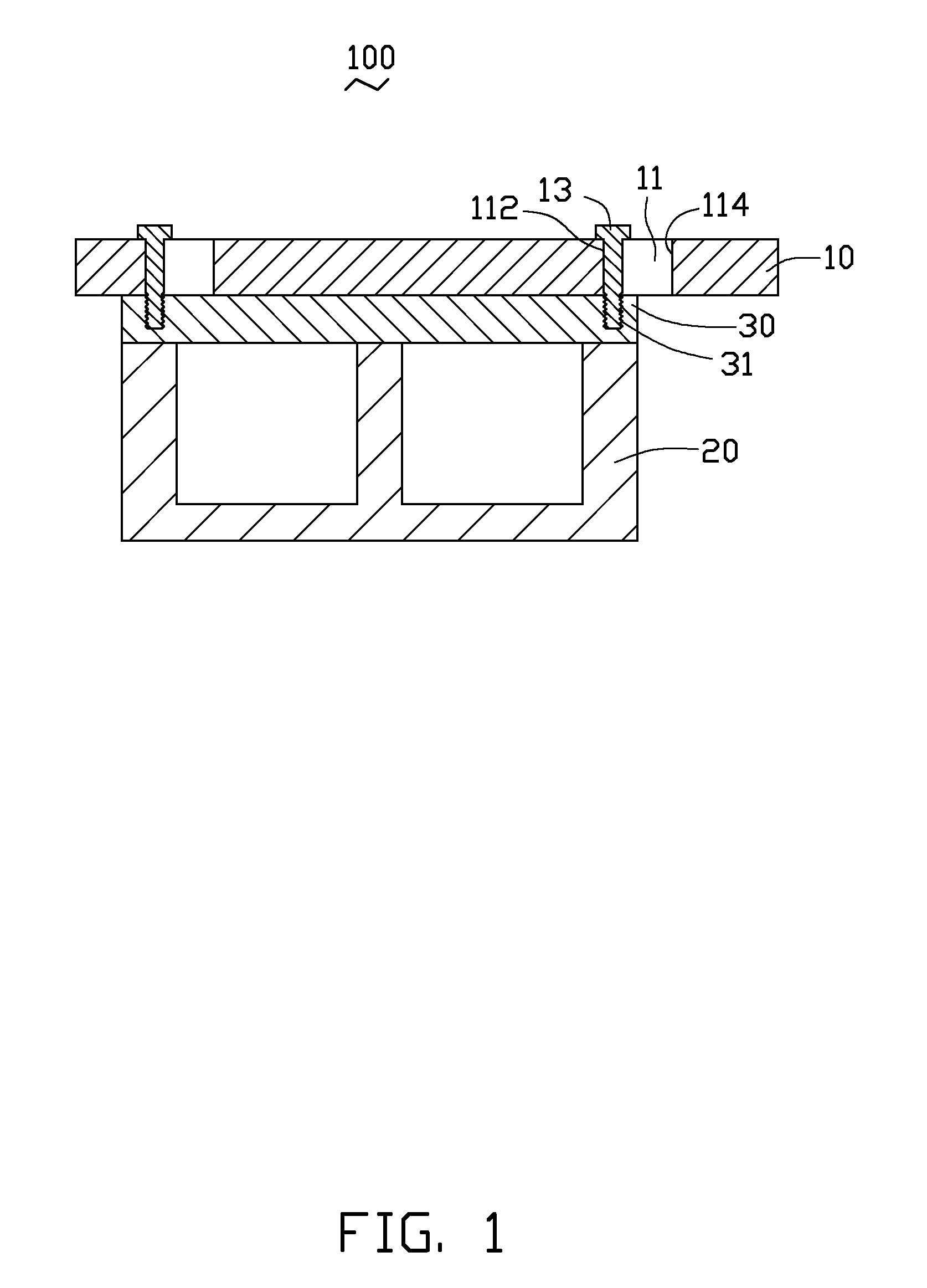
[0014]Referring to FIG. 1, an exemplary embodiment of a target assembly 100 used in magnetron sputtering process is shown. The target assembly 100 includes a target 10, a magnetron 20, a base 30 and a plurality of screws 13. The magnetron 20 is mounted on a first surface of the base 30, the target 10 is adjustably positionable relative to a second surface of the base 30 opposite to the magnetron 20 by the screws 13. The base 30 is made of magnetic material so the magnetron 20 can be attached to the base 30 by the magnetic force. The target 10 is made of metal, alloy, metal oxide or metal nitride.

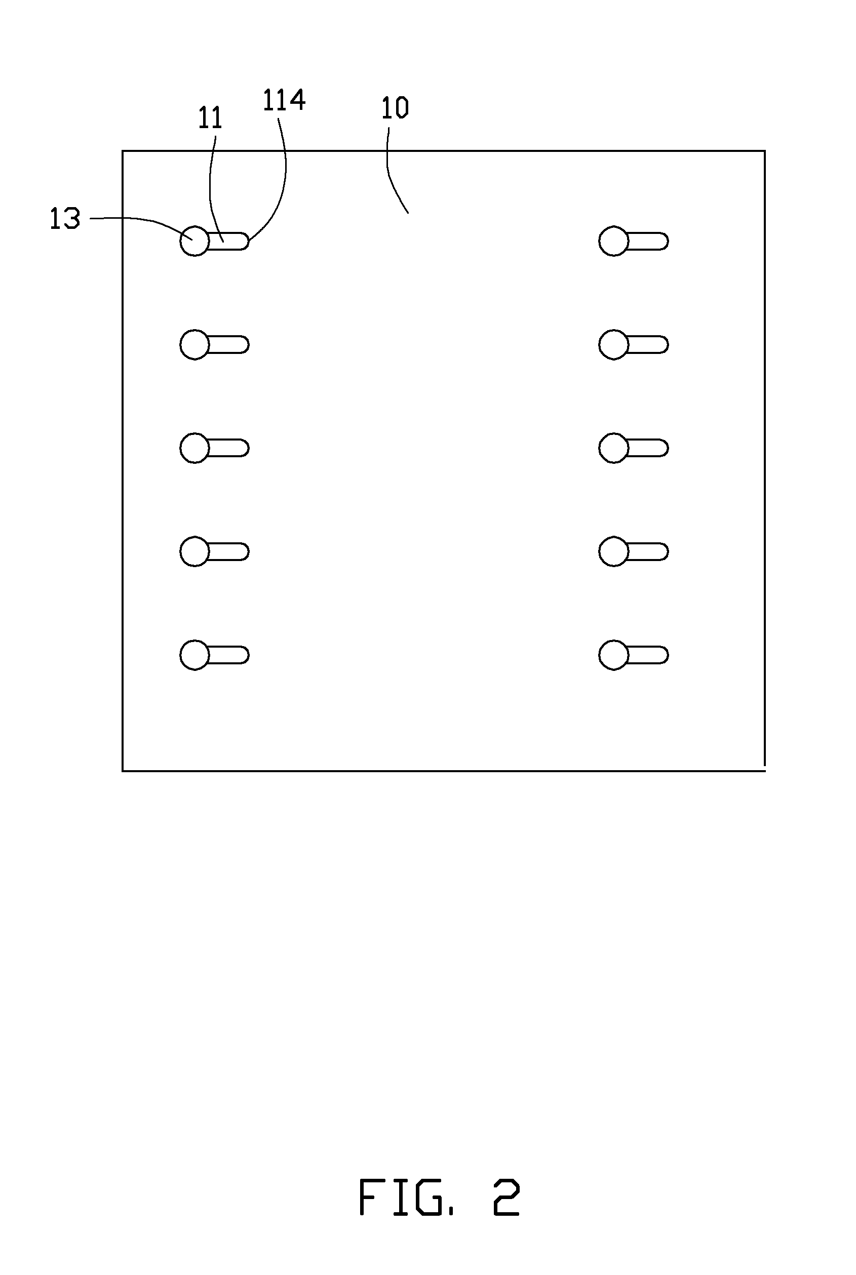
[0015]Referring to FIG. 2, the target 10 defines at least one array of openings 11, in this exemplary embodiment there are two arrays of openings 11. Each opening 11 is substantially rectangle with a first end 112 and a second end 114. In this exemplary embodiment, the first end 112 and the second end 114 are both semi-circular. The base 30 defines equal array of threaded holes 31 correspond...


PUM

PropertyMeasurementUnit
magnetic forceaaaaaaaaaa
areaaaaaaaaaaa
shapeaaaaaaaaaa

Abstract

A target assembly includes a base comprising a first surface and a second surface opposite to the first surface. The base defining a threaded hole; a magnetron mounted on a first surface; a target movably mounted to the second surface, the target defining an opening corresponding to the threaded hole, the opening including a first end and a second end; and a screw. The screw can slide in the opening from the first end to the second end so the position between magnetron and the target is adjusted to adjust the bombarded area of the target.

Description

BACKGROUND[0001]1. Technical Field[0002]The exemplary disclosure generally relates to target assemblies used in magnetron sputtering process.[0003]2. Description of Related Art[0004]Magnetron sputtering is a process whereby atoms are ejected from a solid target due to a bombardment of the target by energetic particles of a magnetron. It is commonly used for thin-film deposition, etching and analytical techniques. Typically, the position between the target and the magnetron cannot be adjusted so the bombarded area of the target cannot be adjusted, and the utilization rate of the target is low.[0005]Therefore, there is room for improvement within the art.BRIEF DESCRIPTION OF THE DRAWINGS[0006]Many aspects of the embodiments can be better understood with reference to the following drawings. The components in the drawings are not necessarily drawn to scale, the emphasis instead being placed upon clearly illustrating the principles of the exemplary target assembly. Moreover, in the drawi...

Claims


Application Information

Patent Timeline
Patent Type & Authority Applications(United States)
IPC IPC(8): C23C14/14C23C14/34
CPCC23C14/3407H01J37/3435H01J37/3417H01J37/34
Inventor CHANG, HSIN-PEICHEN, WEN-RONGCHIANG, HUANN-WUCHEN, CHENG-SHILIN, SHUN-MAO
Owner HONG FU JIN PRECISION IND (SHENZHEN) CO LTD
Why Eureka
Try Eureka