
Quick-change tool holder system for a cutting tool

Active Publication Date: 2012-03-22
BOMAG
View PDF6 Cites 48 Cited by
  • Summary
  • Abstract
  • Description
  • Claims
  • Application Information

AI Technical Summary

Benefits of technology

[0007]Another essential feature of the quick-change tool holder is furthermore the base gripping part. The base gripping part fulfils on the one hand a supporting function and on the other hand a protecting function. The base gripping part is in principle configured in such a manner that it overlaps and embraces a part of the base part in the direction of insertion. The embracing is accomplished in such a manner that the base gripping part grips behind the supporting projection from the point of view of the longitudinal axis of the quick-change tool holder in a hook-like manner. In this region the quick-change tool holder covers the base part with its base gripping part coming from the direction of insertion of the quick-change tool holder and protects it towards the outside. Overall the base gripping part enables the quick-change tool holder to be additionally supported on the base part, at least in the severely stressed state, and in this way, for example, relieves the stress on the bearing body of the quick-change tool holder. This particularly relates to forces acting at least partially obliquely and in particular perpendicularly to the direction of insertion of the quick-change tool holder on the cutting tool or on the quick-change tool holder. The base gripping part therefore enables a particularly advantageous absorption of force by the quick-change tool holder system when the quick-change tool holder system is subjected to forces, for example, during working operation. Specifically, the base gripping part comprises a component projecting from the base body. In relation to the longitudinal axis of the bearing body, the base gripping part projects in particular in the radial direction over the bearing body, preferably towards the underside of the base part with which the base part is fastened on the roller. In principle, the base gripping part can comprise an independent component which is connected to the bearing body, for example, by means of a screw or welded connection. However, it is preferable to manufacture the quick-change tool holder as a solid component, for example as a forged or cast part, so that the bearing body and the base gripping part of the quick-change tool holder are formed in one piece. With the aid of the base gripping part it is possible for the quick-change tool holder to be additionally secured in its position with respect to the base part in the state inserted in the base part and a more favourable absorption of force is obtained. In particular, the base gripping part makes it possible to relieve the stress in particular on the bearing body of the quick-change tool holder. Since the base gripping part comes into engagement with the supporting projection or grips this during insertion of the quick-change tool holder into the quick-change tool holder receptacle of the base part (“direction of insertion”), a type of forced guidance is further achieved by the base gripping part and the supporting projection by which means the relative positioning of the quick-change tool holder to the base part is secured.
[0027]In principle, suitable pastes and greases can additionally be used in the fitting region between the quick-change tool holder and the base part to improve the robustness of the quick-change tool holder system in terms of wear still further. Moreover, it is fundamentally advantageous if the contact surfaces between the base part and the quick-change tool holder are configured to be as flush as possible.

Problems solved by technology

During working operation, the holders for receiving the cutting tools, in particular round-shank picks, are exposed to high stress levels and extremely high wear, on the one hand due to the broken material in the milling box and on the other hand due to the rotating round-shank pick, in particular in the area of the tool shank receiving bore in the tool holder and the contact surface of a wear disk which is possibly provided.
Furthermore, the tool holder becomes worn or destroyed when the tool breaks off, falls out or is worn down.

Method used


Image

  • Quick-change tool holder system for a cutting tool
  • Quick-change tool holder system for a cutting tool
  • Quick-change tool holder system for a cutting tool

Examples


embodiment 200

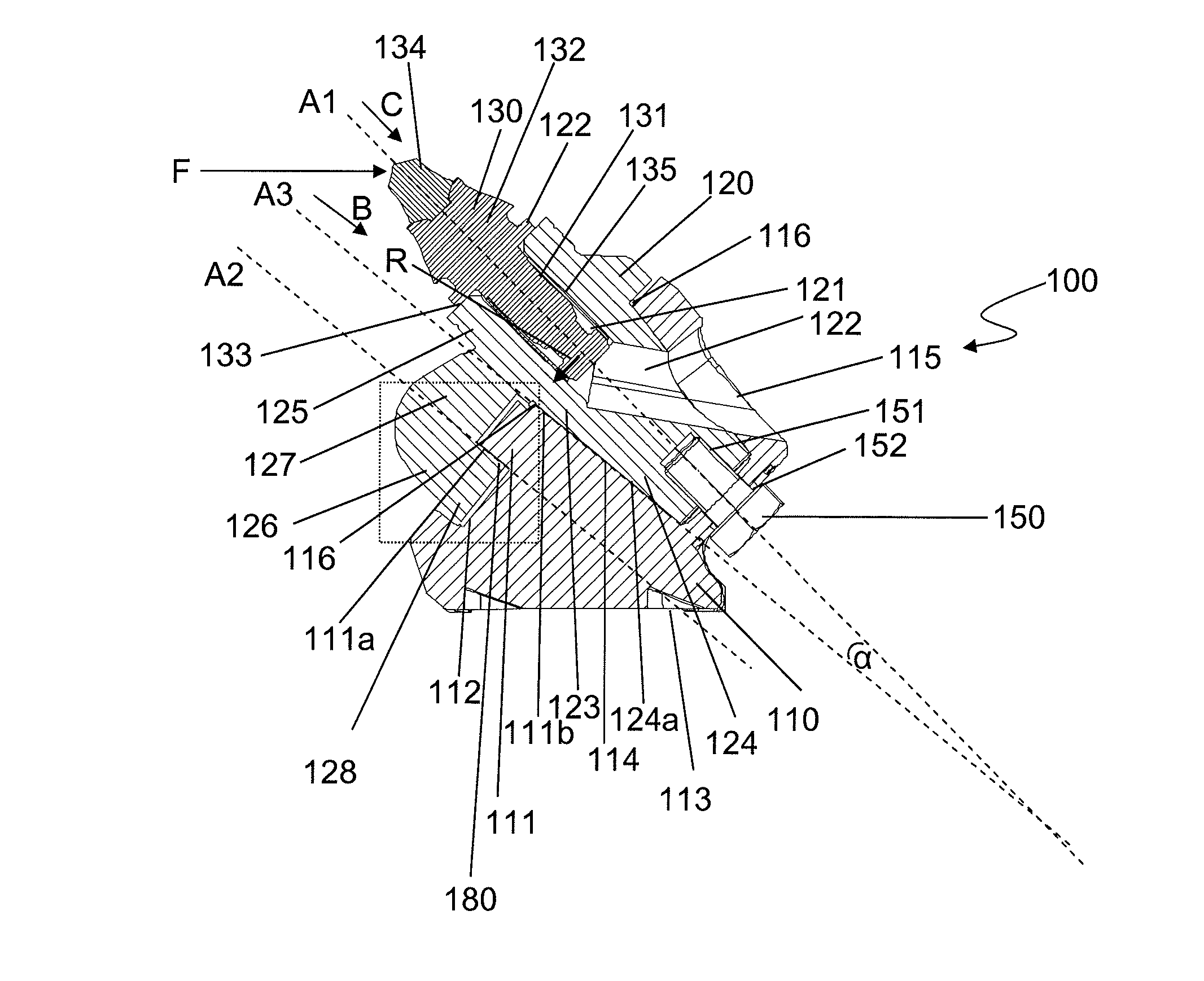
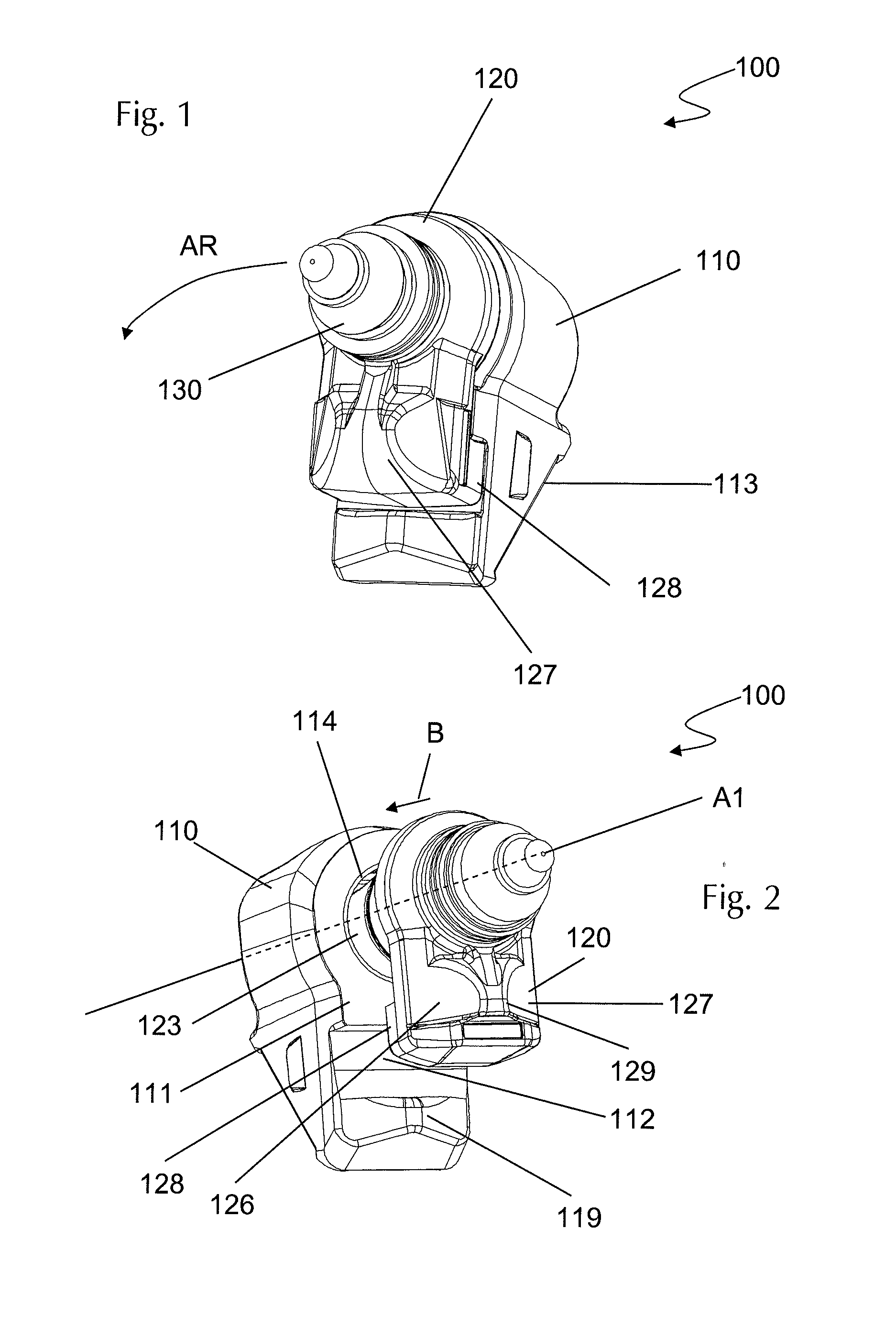
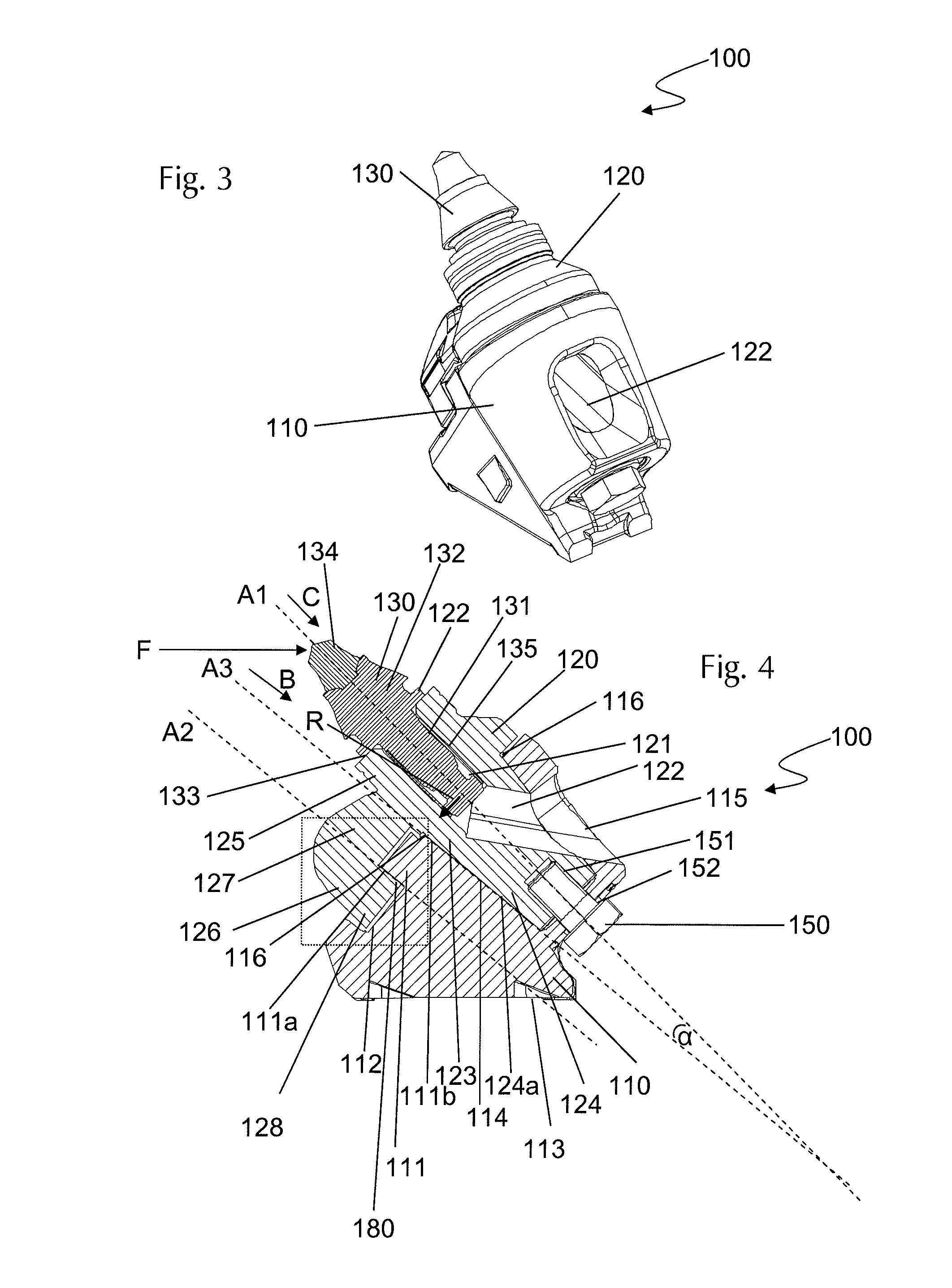
[0056]Specifically this is achieved in the embodiment 200 according to FIGS. 6 to 9 with the circular-segment shaped design of the base-gripping part 226 and the arc-segment shaped configuration of the groove 212. It is important for understanding the functioning of the quick-change tool holder system 200 that the circular paths of the groove 212 and that of the part of the base gripping part 226 facing the quick-change tool holder 220 run concentrically to the axis of rotation D about which the quick-change tool holder 220 is turned to engage with the base part 210 (or unscrewed for dismounting). In the quick-change tool holder system 200, the axis of rotation D is simultaneously the longitudinal axis A1 of the cutting tool receptacle 221.

[0057]Another essential detail lies in the fact that the base gripping part 226 is undercut and thus forms a hook element in the mounted state contrary to the direction of insertion B which secures the quick-change tool holder 220 with respect to ...

exemplary embodiment 100

[0061]In particular FIG. 7 illustrates the essential characteristic of the embodiment of the quick-change tool holder system 200 with the connection between the base part 210 and the quick-change tool holder 220 configured in the manner of a bayonet closure. FIG. 7 shows the dismounting steps starting from the state shown in FIG. 6. Accordingly, the mounting steps for installing the quick-change tool holder 220 in the base part proceed in the reverse order. First, the fastening screw 250 is released, thus releasing the turning prevention of the quick-change tool holder 220 in relation to the base part 210 achieved with the screw 250. In a next step, the quick-change tool holder 220 can then be unscrewed from the bayonet holder about the axis of rotation D in the direction of the arrow P2. To this end, the base gripping part 226 must be twisted until it disengages from the undercut formed in the supporting projection 211. The quick-change tool holder 220 can then be withdrawn from th...


PUM

PropertyMeasurementUnit
Angleaaaaaaaaaa
Shapeaaaaaaaaaa

Abstract

The present invention relates to a quick-change tool holder system, comprising a base part with a quick-change tool holder receptacle and a quick-change tool holder having a cutting tool receptacle configured for insertion into the quick-change tool holder receptacle.

Description

FIELD OF THE INVENTION[0001]The present invention relates to a quick-change tool holder system, comprising a base part and a quick-change tool holder configured to be held in the base part having a cutting tool receptacle for receiving and mounting a cutting tool, in particular a round-shank pick.BACKGROUND OF THE INVENTION[0002]A frequent area of use of generic quick-change tool holder systems is their use in machines for ground preparation, especially in road construction. This frequently involves machines having a driven roller rotatable about a horizontal axis, on which a plurality of ground preparation tools, in particular cutting tools and especially round-shank picks, are arranged. Such machines comprise, for example, stabilisers, recyclers and road millers, in particular cold millers. During working operation, the holders for receiving the cutting tools, in particular round-shank picks, are exposed to high stress levels and extremely high wear, on the one hand due to the bro...

Claims


Application Information

Patent Timeline
IPC IPC(8): E21C35/193E21C35/19
CPCB28D1/188E21C35/191
Inventor ERDMANN, PETERWACHSMANN, STEFFENLAUGWITZ, NIELSMOETZ, KARL-HERMANN
Owner BOMAG
Features
  • Generate Ideas
  • Intellectual Property
  • Life Sciences
  • Materials
  • Tech Scout
  • Unparalleled Data Quality
  • Higher Quality Content
  • 60% Fewer Hallucinations
Learn More