

Piezoelectric Device
a technology of piezoelectric devices and piezoelectric tubes, which is applied in piezoelectric/electrostrictive/magnetostrictive devices, piezoelectric/electrostriction/magnetostriction machines, semiconductor devices, etc., can solve problems such as deterioration of frame bodies, gas or water vapor leakage from outside, and narrow width of frame bodies
- Summary
- Abstract
- Description
- Claims
- Application Information
AI Technical Summary
Benefits of technology
Problems solved by technology
Method used
Image

Examples
first embodiment
100>
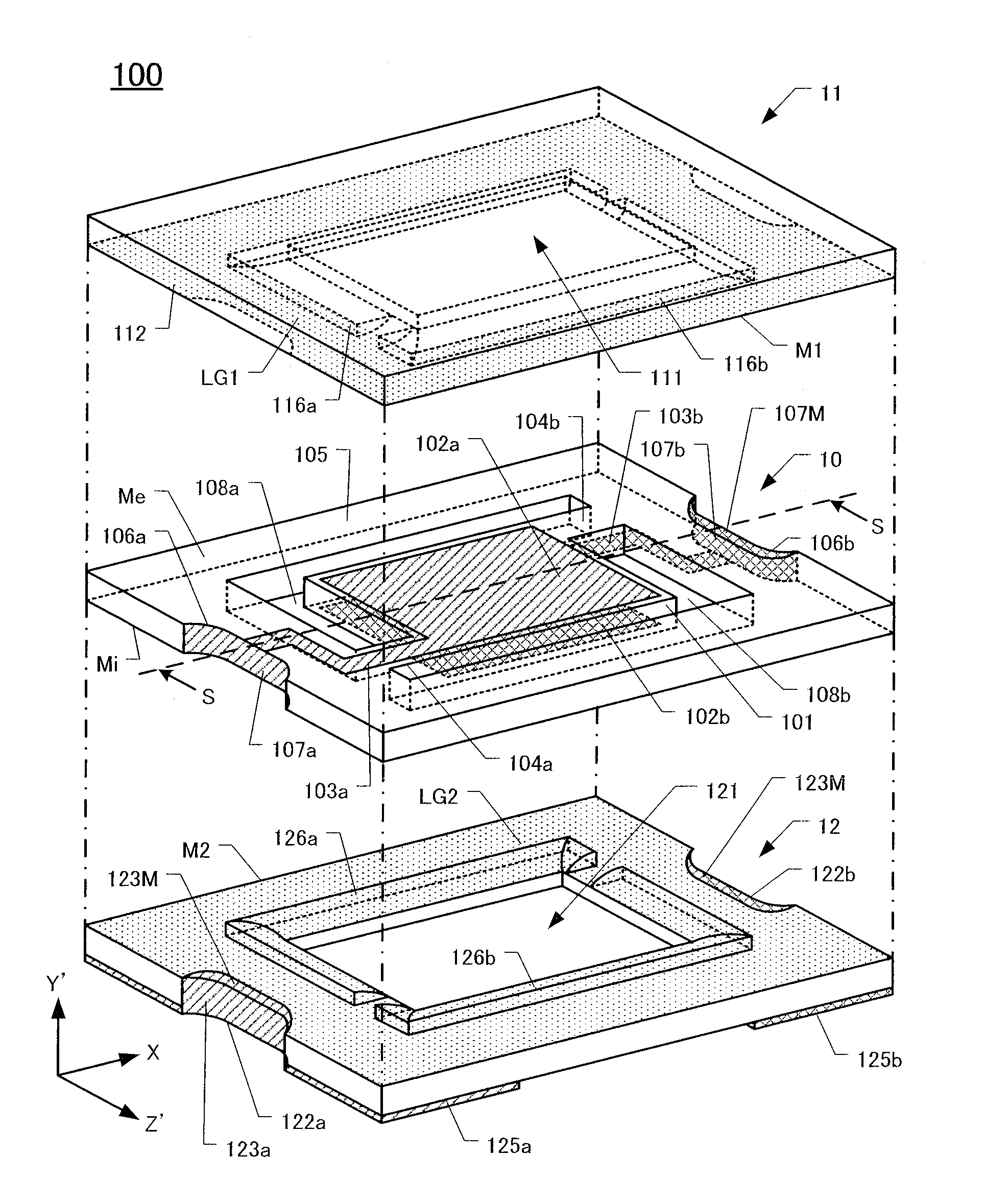
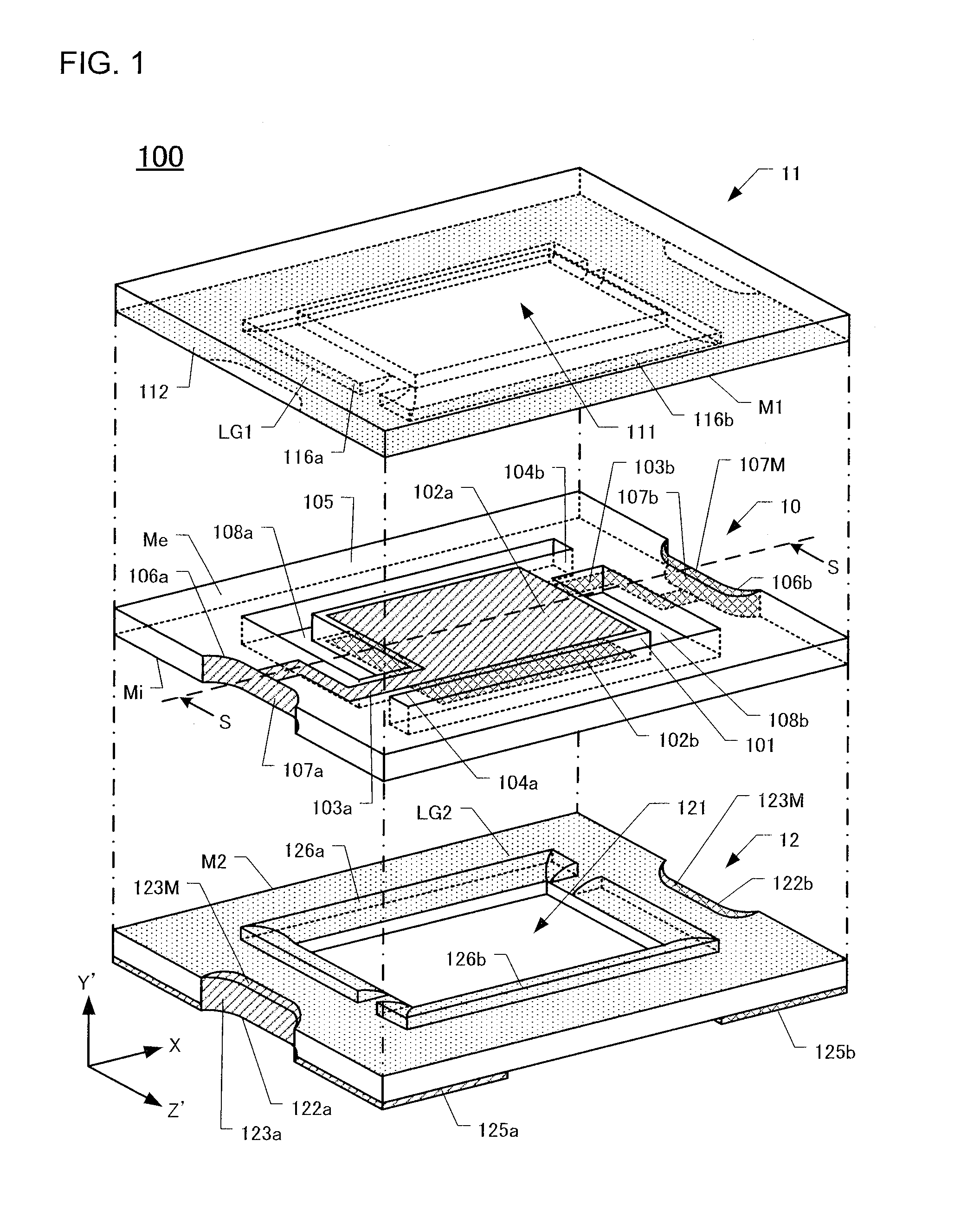
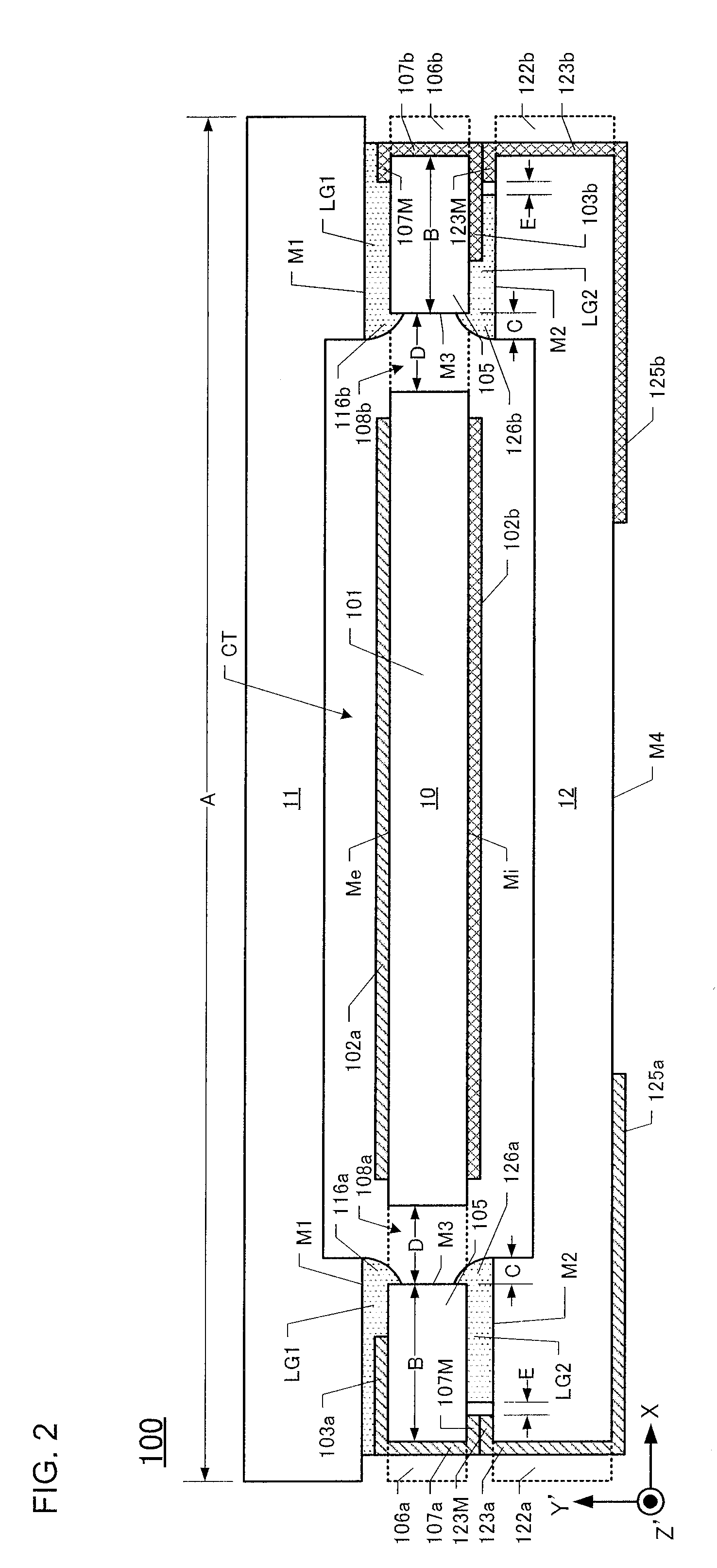
[0034]The overall configuration of a first quartz-crystal vibrating device 100 according to this embodiment is shown in FIGS. 1 and 2. FIG. 1 is an exploded view of the first quartz-crystal vibrating device 100 and FIG. 2 is a cross-section of FIG. 1 taken along S-S line thereof.
[0035]As shown in FIGS. 1 and 2, the first quartz-crystal vibrating piece 100 includes a package lid 11 having a lid recess 111 on the inner main surface, a package base 12 having a base recess 121 on the inner main surface, and a rectangular quartz-crystal frame 10 that is sandwiched between the package lid 11 and package base 12.
[0036]The quartz-crystal frame 10 comprises a quartz-crystal vibrating portion 101 having excitation electrodes 102a and 102b situated on opposed surfaces of the quartz-crystal vibrating portion 101, and a frame body 105 surrounding the quartz-crystal vibrating portion 101. Also, a pair of supporting portions 104a and 104b is disposed in between the quartz-crystal vibrating por...
second embodiment
200>
[0071]The overall configuration of the second quartz-crystal vibrating device 200 is explained using FIG. 9 as a reference. FIG. 9 is a cross-section of the second quartz-crystal vibrating device 200, which corresponds to the S-S line of FIG. 1 in the first embodiment. In this embodiment, components that are similar to corresponding components in the first embodiment have the same reference numerals.
[0072]As shown in FIG. 9, the second quartz-crystal vibrating device 200 includes a quartz-crystal frame 10 that is sandwiched between a package lid 21 and a package base 22. Contrary to the first embodiment, the package lid 21 and the package base 22 have a planar shape without a recessed portion.
[0073]Also, in the second embodiment, the raised low-melting-point glass region 116a explained in the first embodiment combines with the raised low-melting-point region 126a (refer to FIG. 2), thus forming the low-melting-point glass region 206a which is combined from top to bottom. Similar...
third embodiment
300>
[0082]The overall configuration of the third quartz-crystal vibrating device 300 is explained using FIG. 10 as a reference. FIG. 10 is a cross-section of the third quartz-crystal vibrating device 300, which corresponds to the S-S line of FIG. 1 in the first embodiment. In this embodiment, components that are similar to corresponding components in the first embodiment have the same reference numerals.
[0083]As shown in FIG. 10, the third quartz-crystal vibrating device 300 includes a quartz-crystal frame 30 sandwiched between the package lid 11 and package base 12. In the third embodiment, a frame body 305 in the quartz-crystal frame 30 comprises a step portion 309 on inner side surface (quartz-crystal vibrating portion side) and the outer side surface (castellation side) that is recessed from the front surface Me and the back surface Mi. This step portion provides a larger area of the pair of through-hole openings 308a and 308b. According to this configuration, the low-melting-po...
PUM
 Abstract
Description
Claims
Application Information