
Eureka
For R&D, Eureka makes reading and utilizing patents & technical documents easy.
Eureka AIR
Designed for self-driven R&D workflows. Generate viable solutions, solve complex R&D challenges, empower your innovation with AI.

Eureka Materials
Designed for material experts only. Revolutionize your material R&D, from search, analyze, to developing new materials.

TechResearch
Generate reliable direction feasibility study reports for your R&D in just a few steps.

TechSeek
Discover and master advanced knowledge NOW. Basics, ideas, possibilities, all at once.

TechMind
As an expert in R&D Theories, TechMind can generates customized viable solutions instantly.

TechRisk
Analyze your overall solution with one click, know your potential R&D risks in advance.

TechMonitor
Get weekly tech updates, stay abreast of the latest tech innovations and key insights.
Electric motor control device
- Summary
- Abstract
- Description
- Claims
- Application Information
AI Technical Summary
Benefits of technology
Problems solved by technology
Method used
Image

Examples
first embodiment
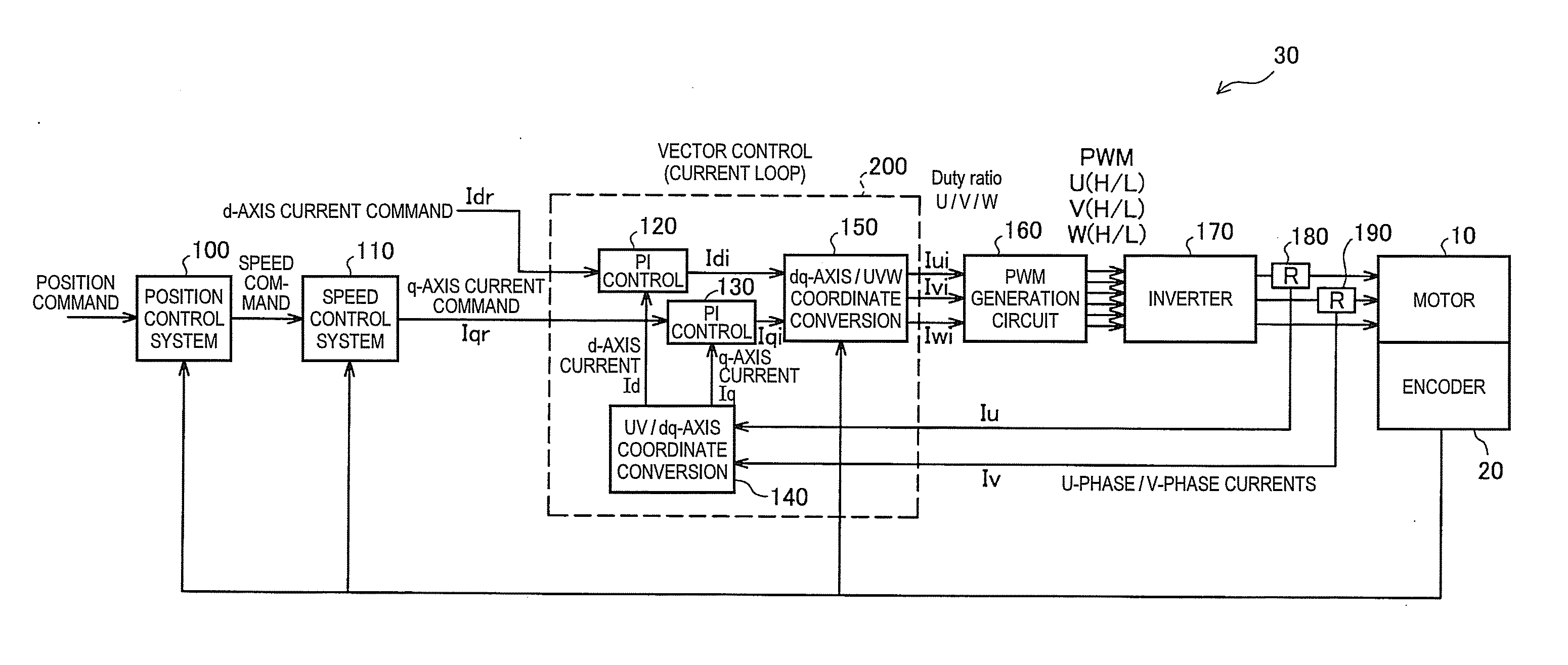
[0042]FIG. 5 is an explanatory diagram showing the T-N characteristics of an electric motor according to a first embodiment of the invention. In the first embodiment, d-axis current control is performed so that the current I does not reach the maximum current Imax until the torque T reaches the maximum torque Tmax. The drive current includes a d-axis current and a q-axis current, and in the vector control of the electric motor, the drive current is controlled by performing the feedback control based on the target values (a d-axis current command value and a q-axis current command value) of the d-axis current and the q-axis current. Taking the d-axis in the direction of the flux of the permanent magnet, the d-axis current represents the component (the excitation current component) used for generating the flux out of the drive current flowing therethrough, and the q-axis current represents the component corresponding to the load torque.
[0043]FIG. 6 is an explanatory diagram showing th...
second embodiment
[0065]FIG. 12 is an explanatory diagram showing the T-N characteristics of an electric motor according to a second embodiment of the invention. In the second embodiment, regarding the d-axis current command value Idr, the torque T is multiplied by the control gain to thereby make the d-axis current command value Idr proportional to the torque, and thus the d-axis current control is performed so that the current is not limited until the torque reaches the maximum torque Tmax set previously. Formula 8 is an arithmetic expression for calculating the d-axis current command value Idr in the second embodiment.
Idr=Kc×T (8)
[0066]In Formula 8, “Kc” denotes the control gain, and can be obtained by an experiment. Further, “T” denotes the torque of the electric motor 10.
[0067]In the second embodiment, the control of suppressing the d-axis current control value to a low level prevents the degradation of the efficiency in the low torque area or in the case of the low rotational speed where no im...
third embodiment
[0071]FIG. 13 is an explanatory diagram showing the T-N characteristics of an electric motor according to a third embodiment of the invention. In the third embodiment, as expressed by Formula 10, the d-axis current command value calculation circuit 210 calculates the q-axis current command value Iqr based on the torque command value to the electric motor 10, and then, calculates the d-axis current command value Idr by multiplying the difference (ω−ωbs) between the rotational speed ω of the electric motor and the previously determined base rotational speed ωbs of the electric motor, the q-axis current command value Iqr, and the control gain by each other.
Idr=Kd×Iqr×(ω−ωbs) (10)
[0072]In Formula 10, “Kd” denotes the control gain, and can be obtained by an experiment. It should be noted that in the present embodiment the d-axis current command value calculation circuit 210 sets the d-axis current command value Idr to zero if the torque is equal to or lower than the previously determine...
PUM
 Abstract
Description
Claims
Application Information
 - R&D Engineer
- R&D Manager
- IP Professional
- Industry Leading Data Capabilities
- Powerful AI technology
- Patent DNA Extraction
Browse by: Latest US Patents, China's latest patents, Technical Efficacy Thesaurus, Application Domain, Technology Topic, Popular Technical Reports.
© 2024 PatSnap. All rights reserved.Legal|Privacy policy|Modern Slavery Act Transparency Statement|Sitemap|About US| Contact US: help@patsnap.com