Lead-angle control method and device for operating permanent magnet synchronous motor in flux weakening regions

a technology of synchronous motor and lead-angle control, which is applied in the direction of electronic commutation motor control, motor/generator/converter stopper, dynamo-electric converter control, etc., can solve the problems of limiting the maximum speed of the pmsm, and affecting the operation of the motor. , to achieve the effect of reducing the error of speed control, improving system performance and reliability

Inactive Publication Date: 2006-06-22
LG ELECTRONICS INC
View PDF9 Cites 21 Cited by
  • Summary
  • Abstract
  • Description
  • Claims
  • Application Information

AI Technical Summary

Benefits of technology

[0018] According to the present invention, since the present invention provides speed control in flux weakening regions by compensating lead-angle components of an instruction curren

Problems solved by technology

Consequently, it causes a current applied to the motor to be reduced, which limits the maximum speed of the PMSM.
However, in such a flux weakening control system operated along an optimum trajectory, as shown in FIG. 1, there is a problem in that it is not possible to move from a point A to a point B in the current/voltage limi

Method used


Image

  • Lead-angle control method and device for operating permanent magnet synchronous motor in flux weakening regions
  • Lead-angle control method and device for operating permanent magnet synchronous motor in flux weakening regions
  • Lead-angle control method and device for operating permanent magnet synchronous motor in flux weakening regions

Examples


Embodiment Construction

[0025] Exemplary embodiments in accordance with the present invention will now be described in detail with reference to the accompanying drawings. In the following description, a detailed description of well-known functions and configurations incorporated herein will be omitted when it may make the subject matter of the present invention rather unclear.

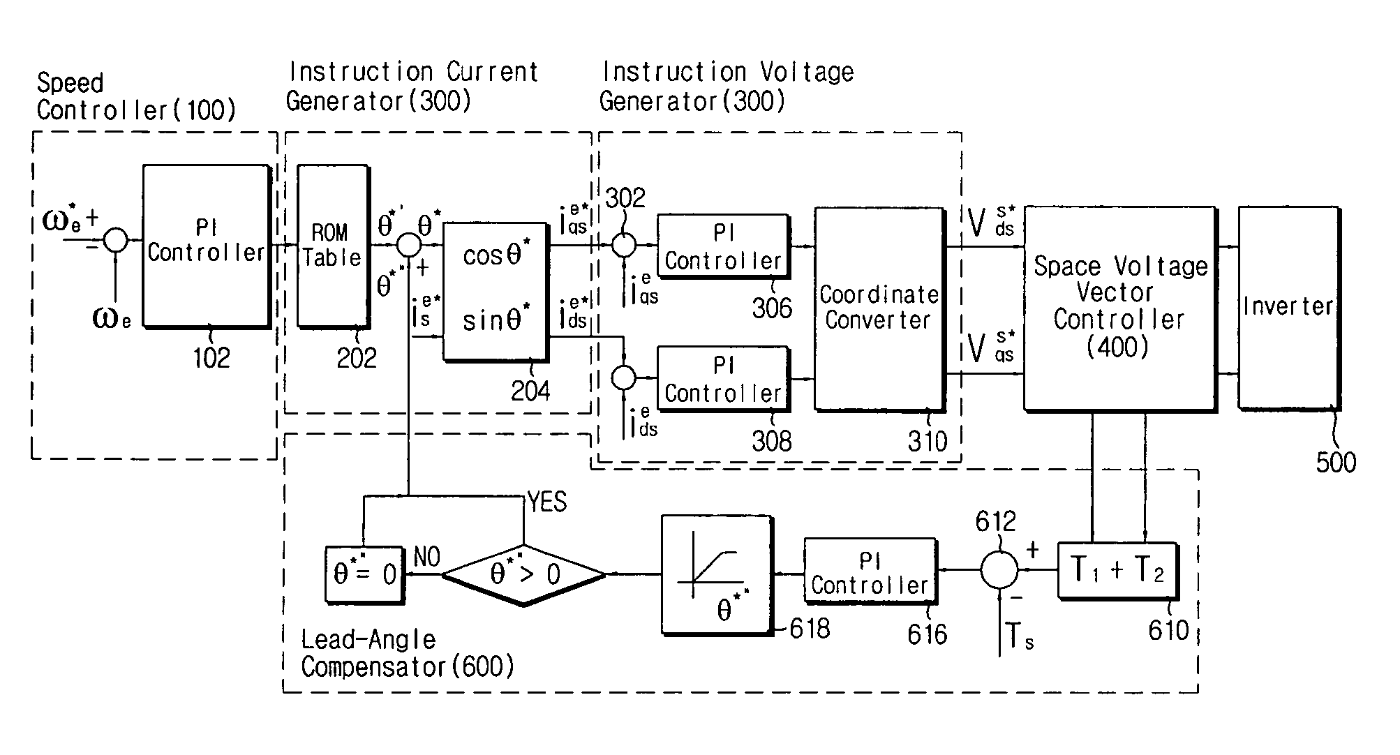
[0026]FIG. 4 is a block diagram showing a construction of a lead-angle control device in a motor control system in accordance with an embodiment of the present invention. FIG. 5 is a flow chart showing lead-angle control of a motor control system in accordance with an embodiment of the present invention.

[0027] As shown in FIG. 4, a lead-angle control device according to the present invention comprises a speed controller 100, an instruction current generator 200, an instruction voltage generator 300, a space voltage vector controller 400, and a lead-angle compensator 600.

[0028] Similar to a typical motor control system, the speed co...


PUM


Abstract

A lead-angle control device according to the present invention includes: a space voltage vector controller calculating effective vector application times necessary for obtaining output voltage vectors of an inverter from stationary-coordinate-system instruction voltage components; a lead-angle compensator comparing the sum of the effective vector application times with a sampling period, and generating lead-angle compensation values; a speed controller generating an instruction current for compensating an error caused by a difference between an instruction speed and a current speed; an instruction current generator which generates a rotating-coordinate-system instruction current component by extracting a lead-angle component at a point where maximum torque-per-ampere can be obtained from the magnitude of the instruction current and performing a mathematical calculation on the magnitude of the instruction current and a lead-angle component; and an instruction voltage generator generating a stationary-coordinate-system instruction voltage component from the rotating-coordinate-system instruction current component.

Description

BACKGROUND OF THE INVENTION [0001] This application claims the priority of Korean Patent Application No. 2004-108945, filed on Dec. 20, 2004, in the Korean Intellectual Property Office, the disclosure of which is incorporated herein in its entirety by reference. [0002] 1. Field of the Invention [0003] The present relates to a permanent magnet synchronous motor and, more particularly, to a lead-angle control method and device for speed control in flux weakening regions. [0004] 2. Description of Related Art [0005] In recent years, permanent magnet synchronous motors (PMSMs) have been widely used in a variety of industrial applications due to their high efficiency characteristics and high torque characteristics over an inertial force. There is an advantage in that the PMSMs can be controlled at high speeds in a constant power region as well as a constant torque region due to their structural characteristics. Along with the advantage, as the PMSMs are required to be operated at higher s...

Claims


Application Information

Patent Timeline
IPC IPC(8): H02K23/16
CPCH02P21/06H02P25/021H02P25/024
Inventor YANG, SOON-BAEPARK, SUNG-MINKIM, TAE-WONKIM, TAE-KYUNG
Owner LG ELECTRONICS INC
Why Eureka
Try Eureka