Eureka AIR delivers breakthrough ideas for toughest innovation challenges, trusted by R&D personnel around the world.

Control device for vehicle electric drive motor and vehicle with the same

A technology for vehicle driving and control devices, which is applied in battery/fuel cell control devices, control devices, electric vehicles, etc., and can solve problems such as difficulty in coping, reducing exhaust environmental protection, and inability to deal with it.

Active Publication Date: 2012-08-08
HITACHI LTD
View PDF5 Cites 23 Cited by
  • Summary
  • Abstract
  • Description
  • Claims
  • Application Information

AI Technical Summary

Problems solved by technology

[0007] However, when it is intended to apply the battery warm-up operation (cold start operation) of the above-mentioned Patent Document 1 to a vehicle whose driving source is only an electric motor, that is, a so-called electric vehicle, since the battery warm-up operation of Patent Document 1 uses the internal combustion engine The operation and the d-axis current of the driving motor are used together, so it cannot cope with
That is, when the technology of Patent Document 1 is applied to an electric vehicle, since only the d-axis current of the vector control flows during cold start (when battery warm-up is required), it can be handled when the vehicle is stopped, but in the driving mode ( In the mode in which the required drive torque to the motor is generated via the accelerator), since the q-axis current (torque component current) is generated, only the d-axis current cannot flow, which is difficult to deal with
On the other hand, in a hybrid vehicle, during battery warm-up operation, only the d-axis current flows through the driving motor (the q-axis current is zero: the driving motor does not rotate), and the vehicle is driven exclusively by the internal combustion engine. Therefore, from the viewpoint of environmental protection such as reducing exhaust emissions, the characteristics of hybrid vehicles cannot be fully utilized.

Method used


Image

  • Control device for vehicle electric drive motor and vehicle with the same
  • Control device for vehicle electric drive motor and vehicle with the same
  • Control device for vehicle electric drive motor and vehicle with the same

Examples


Embodiment 1

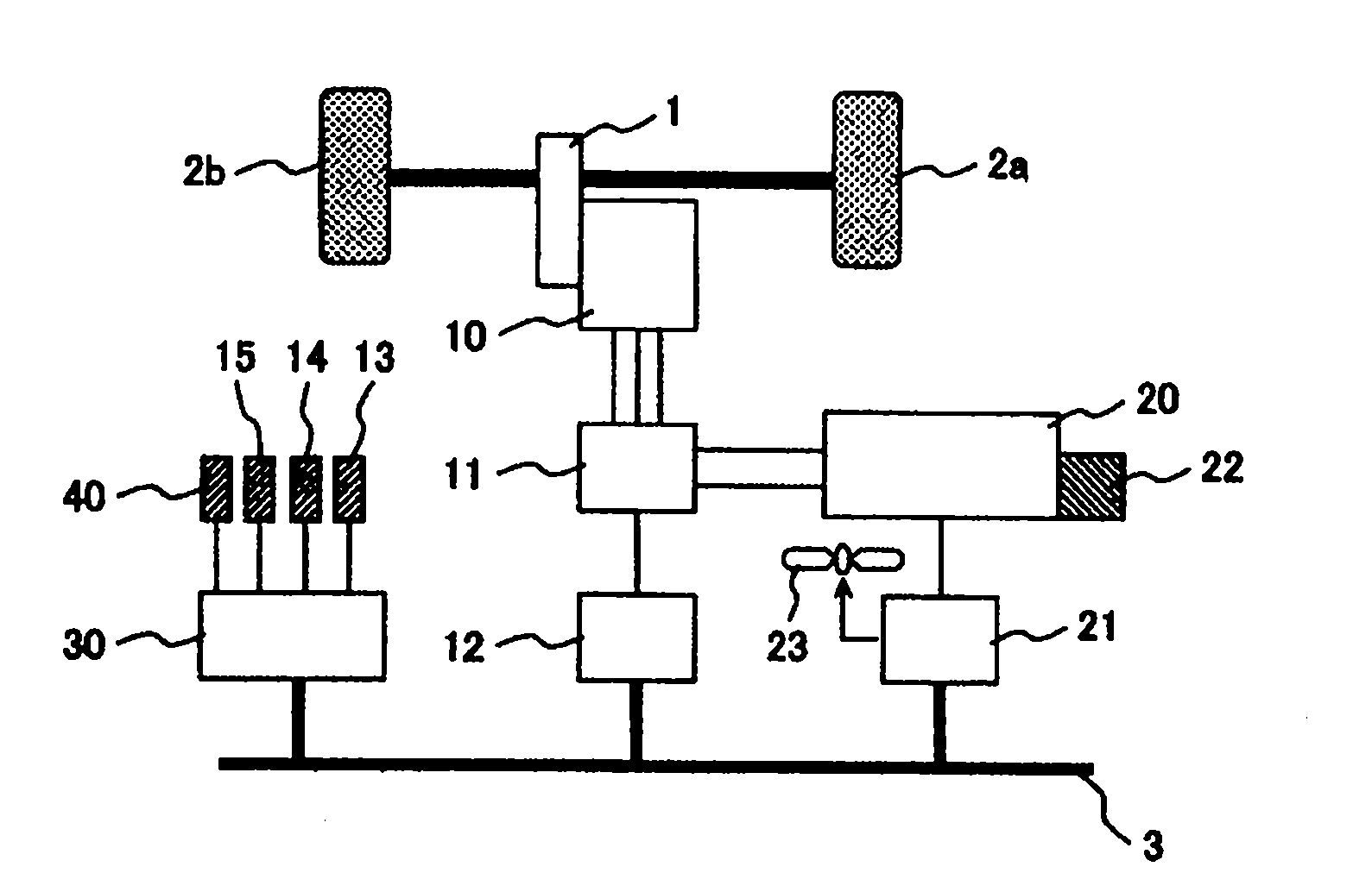
[0029] figure 1 It is a schematic diagram of a vehicle equipped with a motor control device according to the first embodiment of the present invention, and as an example, a schematic diagram of an electric vehicle having a driving motor 10 for vehicle running as a driving source is shown.

[0030] figure 1 The vehicle according to the embodiment has the following configuration as an ECU (Electronic Control Unit): a battery ECU 21; a motor ECU (motor control unit) 12 that controls the motor 10; and a vehicle ECU 30 that controls the entire vehicle. . The battery ECU 21 calculates the inter-terminal voltage of the battery 20 serving as the power supply for the vehicle, the charging and discharging current, and the accumulated state of charge (SOC) based on the charging and discharging current, or obtains the battery temperature generated by the battery temperature sensor 22, etc., and performs Management of the battery 20 such as charging and discharging current. In addition,...

Embodiment 2

[0066] Image 6 It is a schematic diagram of a vehicle equipped with a motor control device according to a second embodiment of the present invention. In the embodiment, not only the self-heating of the battery with d-axis current and q-axis current can be used, but also the heat generated by the motor or inverter can be used to preheat the battery.

[0067] about Image 6 added to the composition of figure 1 Parts with the same symbols have the same functions, and therefore descriptions thereof are omitted. In this example, figure 1 The vehicle of this invention is provided with the same battery ECU21, motor ECU12, and vehicle ECU30 as the first embodiment.

[0068] In this embodiment, not only the battery warm-up based on the self-heating of the battery using the d-axis current and q-axis current as in the first embodiment is performed, but also the heat generated in the vehicle drive motor 10 or the inverter 11 is passed through The cooling water and air are moved to t...

Embodiment 3

[0083] Figure 7 It is a flowchart showing motor current control during battery warm-up operation applied to the vehicle according to the third embodiment of the present invention.

[0084] The vehicle configuration of this embodiment is the same as that of the first embodiment, and d-axis current control and q-axis current control are performed based on the battery temperature and the required drive torque signal during warm-up operation as in the first embodiment, However, the difference from the first embodiment is that when the vehicle is stopped, the motor ECU 12 not only performs the warm-up operation of the d-axis current, but also does not make the q-axis current zero, but is set so that when the brake is released, the vehicle can be activated. The q-axis current value of the driving torque for creeping.

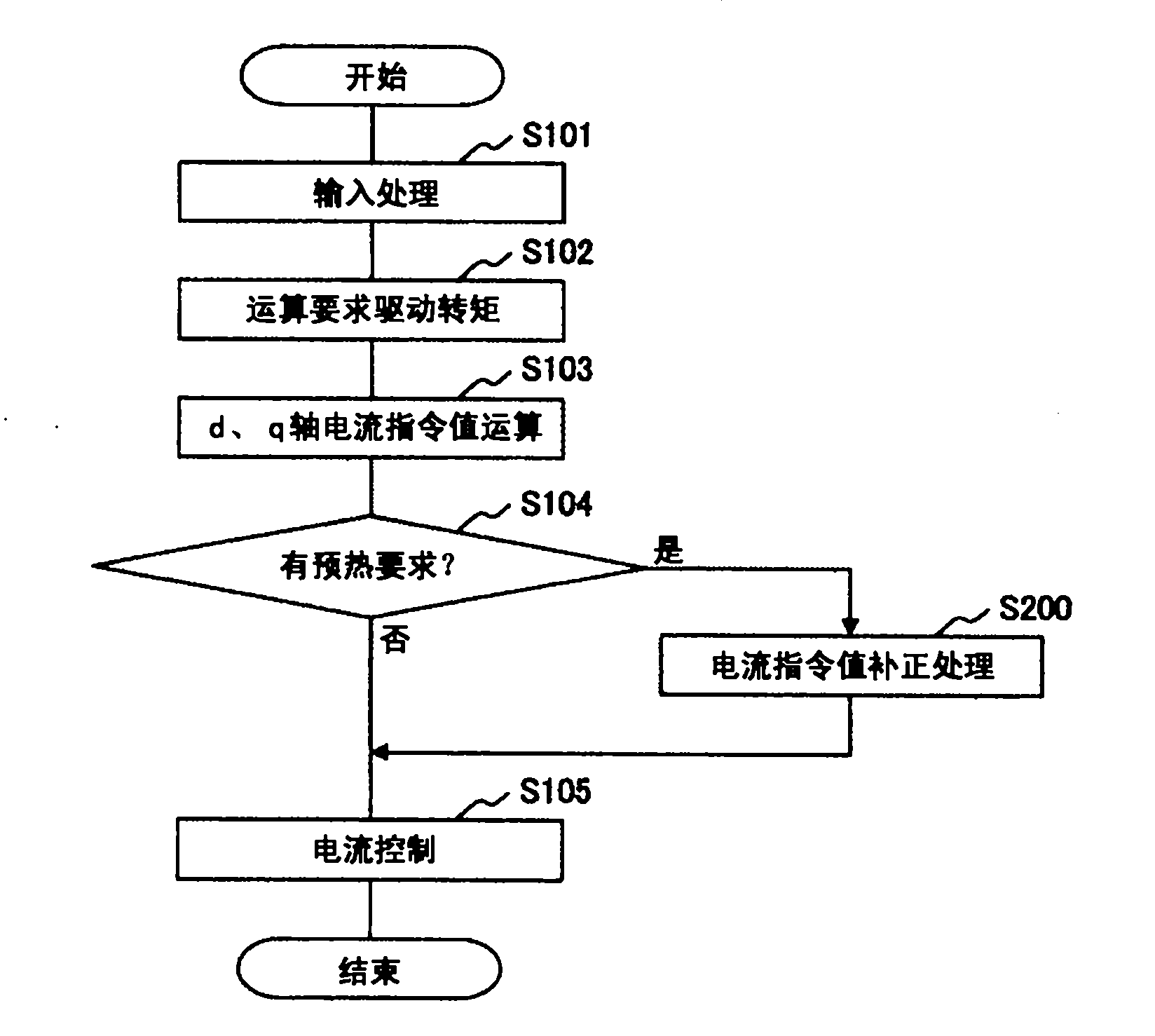
[0085] In the following, for such motor control, the Figure 7 The flow chart is described. exist Figure 7 In the flow chart, with image 3 In the shown flowch...


PUM


Abstract

A controller for vector-controlled motor of vehicle judges whether a battery needs to be warmed up in accordance with an output of a battery temperature sensor, and when the battery needs to be warmed up, in situation (i) where the vehicle is stopped, sets a q-axis current value of the motor at zero, or when a brake is released from the situation (i), sets a q-axis current at a value corresponding to a drive torque for a vehicle creep operation, and sets a d-axis current at a value for battery warm-up. When the battery needs to be warmed up in situation (ii) where the vehicle is running, the controller sets a q-axis current at a value corresponding to a drive torque of vehicle running and sets a d-axis current at a value for the battery warm-up in relation to the q-axis current value.

Description

technical field [0001] The present invention relates to a control device for a drive motor for driving a vehicle and a vehicle (for example, an electric vehicle, a hybrid vehicle, etc.) equipped with the control device, and more particularly to motor control for controlling electric power supplied from a battery to a motor subjected to vector control device. Background technique [0002] Conventionally, a chargeable and dischargeable secondary battery (hereinafter referred to as a battery) is known as a motor power source of an electric vehicle or a hybrid vehicle using an electric motor as a driving source for vehicle running. The battery has a property that its charge-discharge characteristics decrease when the battery temperature decreases, and it is preferable to preheat the battery when the vehicle is stopped for a long time and then restarted from a cold start in winter or in cold regions where the external temperature is low. [0003] As a prior art for battery warm-...

Claims


Application Information

Patent Timeline
Patent Type & Authority Applications(China)
IPC IPC(8): B60L11/18
CPCY02T10/643B60L2240/545B60L15/025B60L11/1875Y02T10/705Y02T10/642Y02T10/7005B60L11/1872H02P21/06B60L58/25B60L58/27Y02T10/64Y02T10/70
Inventor 儿岛隆生横山笃
Owner HITACHI LTD
Why Eureka
Eureka Blog
Learn More