
Vector control device for induction motor
A technology of induction motor and vector control, applied in motor generator control, electronic commutation motor control, vector control system and other directions, can solve the problems of large rotation speed observation error, system instability, and inability to guarantee algorithm stability.
- Summary
- Abstract
- Description
- Claims
- Application Information
AI Technical Summary
Problems solved by technology
Method used
Image

Examples
specific Embodiment approach 1
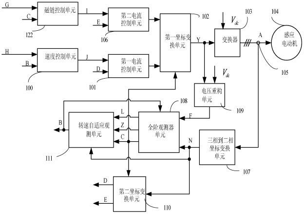
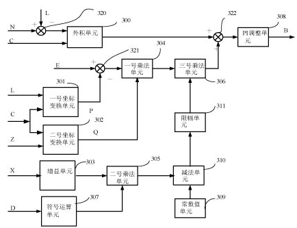
[0012] Specific implementation mode one: the following combination Figure 1 to Figure 3 This embodiment will be specifically described. This embodiment includes a current sensor 105, a converter 103, a first coordinate transformation unit 102, a second coordinate transformation unit 110, a three-phase to two-phase coordinate transformation unit 107, a voltage reconstruction unit 109, a first current control unit 101, a second Two current control unit 106, speed control unit 100, flux linkage control unit 122, full-order observer unit 108 and rotational speed adaptive observation unit 111,
[0013] After the stator current A of the induction motor 104 is sampled by the current sensor 105, it is sent to the three-phase to two-phase coordinate transformation unit 107 for coordinate transformation of the α-β stationary coordinate axis system. The second coordinate transformation unit 110 is based on the full-order observer unit 108 The observed angle of the observed value C of t...
PUM
 Abstract
Description
Claims
Application Information