Exhaust manifold and exhaust system employing same

An exhaust manifold and exhaust branch pipe technology, which is applied to exhaust devices, mufflers, engine components, etc., can solve problems such as the inability to meet the requirements of high performance and low emission of the engine, and the inability to effectively improve low-speed performance. Low-speed performance, the effect of reducing the level of mutual interference

Inactive Publication Date: 2011-01-26
CHERY AUTOMOBILE CO LTD
View PDF11 Cites 4 Cited by
  • Summary
  • Abstract
  • Description
  • Claims
  • Application Information

AI Technical Summary

Problems solved by technology

But because the cross-section of the exhaust manifold is too large and the length is relatively short, the airflow in the first exhaust branch pipe and the fourth exhaust branch pipe and the airflow in the second exhaust branch pipe and the third exhaust branch pipe will be separa

Method used


Image

  • Exhaust manifold and exhaust system employing same
  • Exhaust manifold and exhaust system employing same
  • Exhaust manifold and exhaust system employing same

Examples


Embodiment Construction

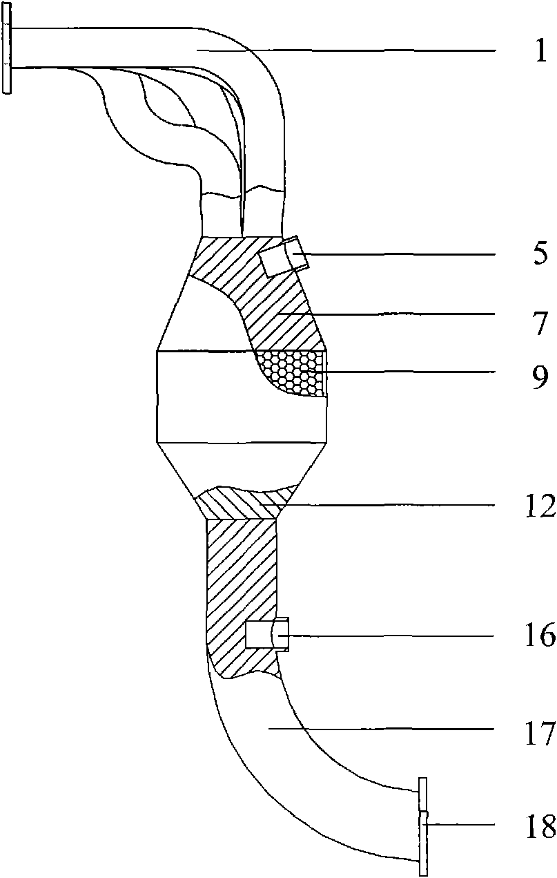
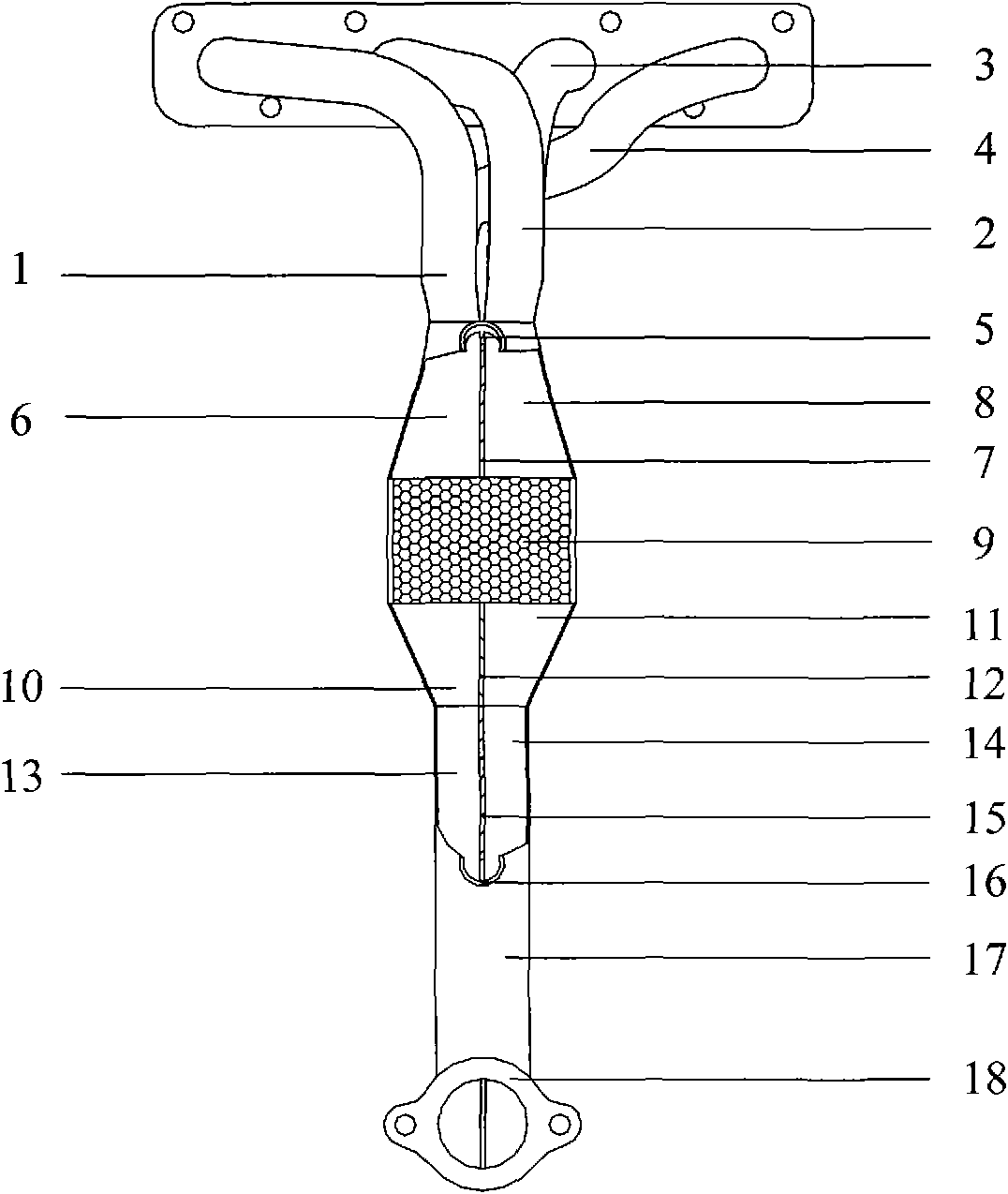
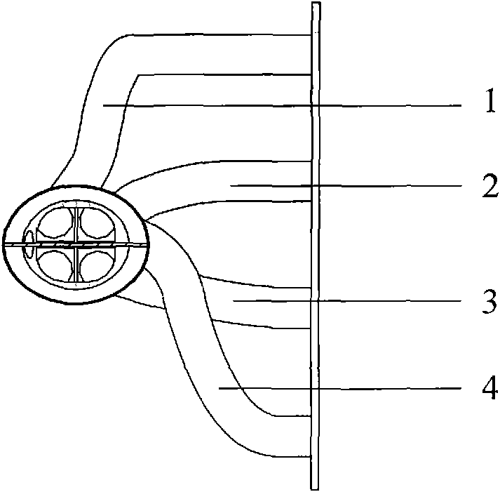
[0024] Such as Figure 1-Figure 3 As shown, in the embodiment of the present invention, the exhaust system of a four-cylinder engine is taken as an example for description. Such as figure 1 As shown in , from the left are the first exhaust branch pipe 1, the second exhaust branch pipe 2, the third exhaust branch pipe 3 and the fourth exhaust branch pipe 4, corresponding to the first cylinder, the second cylinder, and the third exhaust branch pipe of the engine respectively. cylinder and fourth cylinder. The engine ignition is sequentially ignited in the order of the first cylinder, the third cylinder, the fourth cylinder, the second cylinder and the first cylinder.

[0025] The exhaust manifold in the exhaust system mainly includes: a first exhaust branch pipe, a second exhaust branch pipe, a third exhaust branch pipe and a fourth exhaust branch pipe respectively connected with each cylinder, and a spindle-shaped pre-exhaust pipe. The catalytic converter, the exhaust front ...


PUM


Abstract

The invention discloses an exhaust manifold and an exhaust system employing the same. The exhaust manifold comprises a plurality of exhaust branches, a first front end chamber, a second front end chamber, a precatalyst carrier, a first rear end chamber, a second rear end chamber and an exhaust front pipe, wherein the first rear end chamber is communicated with the first front end chamber, and the second rear end chamber is communicated with the second front end chamber. Airflow of the first front end chamber and the airflow of the second front end chamber pass through the precatalyst carrier, and then pass through the corresponding first rear end chamber and second rear end chamber respectively to reach the exhaust front pipe. In the invention, one part of waste gas exhausted by each of cylinders passes through the first front end chamber and the other part of waste gas passes through the second front end chamber and then the waste gas directly enters the precatalyst carrier, so a distance that the waste gas enters the precatalyst carrier is shortened; and then the waste gas passes through the first rear end chamber and the second rear end chamber respectively and then reaches the exhaust front pipe respectively, namely, a mode of 4-2-2-1 similarly. Therefore, the length of exhausting independently in the exhaust manifold is extended, mutual interference degree of the airflow among the cylinders is reduced obviously, and the low speed performance of an engine is improved.

Description

technical field [0001] The invention relates to an exhaust system of an internal combustion engine, more specifically, to an exhaust manifold and an exhaust system using the exhaust manifold. Background technique [0002] With the strengthening of environmental protection awareness, the treatment of automobile exhaust after the exhaust of internal combustion engines of automobiles is also paid more and more attention. The exhaust system of a car includes an exhaust manifold that communicates with each cylinder of the internal combustion engine and a subsequent exhaust catalytic system. For the four-cylinder engine, there are four air passages, and the exhaust manifold is also provided with four exhaust branch pipes to connect with the four air passages. [0003] Existing exhaust manifolds mainly have two structural forms: [0004] One is that the exhaust manifolds that communicate with each cylinder are directly connected to the catalytic converter, which is the 4-1 form f...

Claims


Application Information

Patent Timeline
IPC IPC(8): F01N13/10
Inventor 王伟李玉琦张志福
Owner CHERY AUTOMOBILE CO LTD
Why Eureka
Try Eureka