
Systems and Methods for Measuring Electrical Power Usage in a Structure and Systems and Methods of Calibrating the Same

a technology of electrical power consumption and electrical circuit breaker panel, which is applied in the field of systems and methods for monitoring electrical power, and can solve problems such as the difficulty of accurately measuring the magnetic field of one or more main electrical power conductors on the surface of electrical circuit breaker panels

Active Publication Date: 2012-03-22
BELKIN INT
View PDF6 Cites 54 Cited by
  • Summary
  • Abstract
  • Description
  • Claims
  • Application Information

AI Technical Summary

Problems solved by technology

It is, therefore, difficult to measure accurately the magnetic field of the one or more main electrical power conductors at a surface of the electrical circuit breaker panel.

Method used


Image

  • Systems and Methods for Measuring Electrical Power Usage in a Structure and Systems and Methods of Calibrating the Same
  • Systems and Methods for Measuring Electrical Power Usage in a Structure and Systems and Methods of Calibrating the Same
  • Systems and Methods for Measuring Electrical Power Usage in a Structure and Systems and Methods of Calibrating the Same

Examples


first embodiment

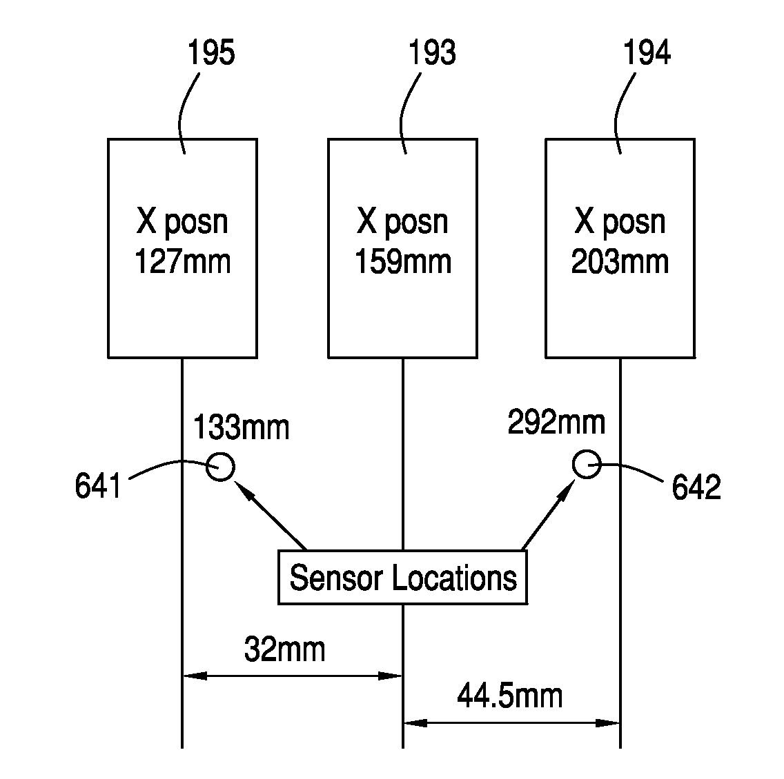
[0078]FIG. 6 illustrates an example of electrical current sensor 211, according to the In these examples, electrical current sensor can include: (a) one or more sensors 641 and 642; (b) one or more amplifiers 647 and 648; (c) one or more filters 649 and 650; (d) one or more phase detectors 651; (e) at least one differential amplifier 652; and (f) at least one digitizer 653.

[0079]In some examples, system 100 can be configured to assist the user in the proper placement of sensing device 110 by indicating the proper placement with user communications module 214. In some examples, system 100 can determine proper placement by detecting an approximately 180 degree phase difference between sensors 641 and 642 that are disposed on opposite sides of a conductor (i.e., electrical power conductor 193 or 194). In the same or different examples, user communications module 214 can be co-located with sensing device 110 or user communications module 214 can be used and can be remote and linked to ...

third embodiment

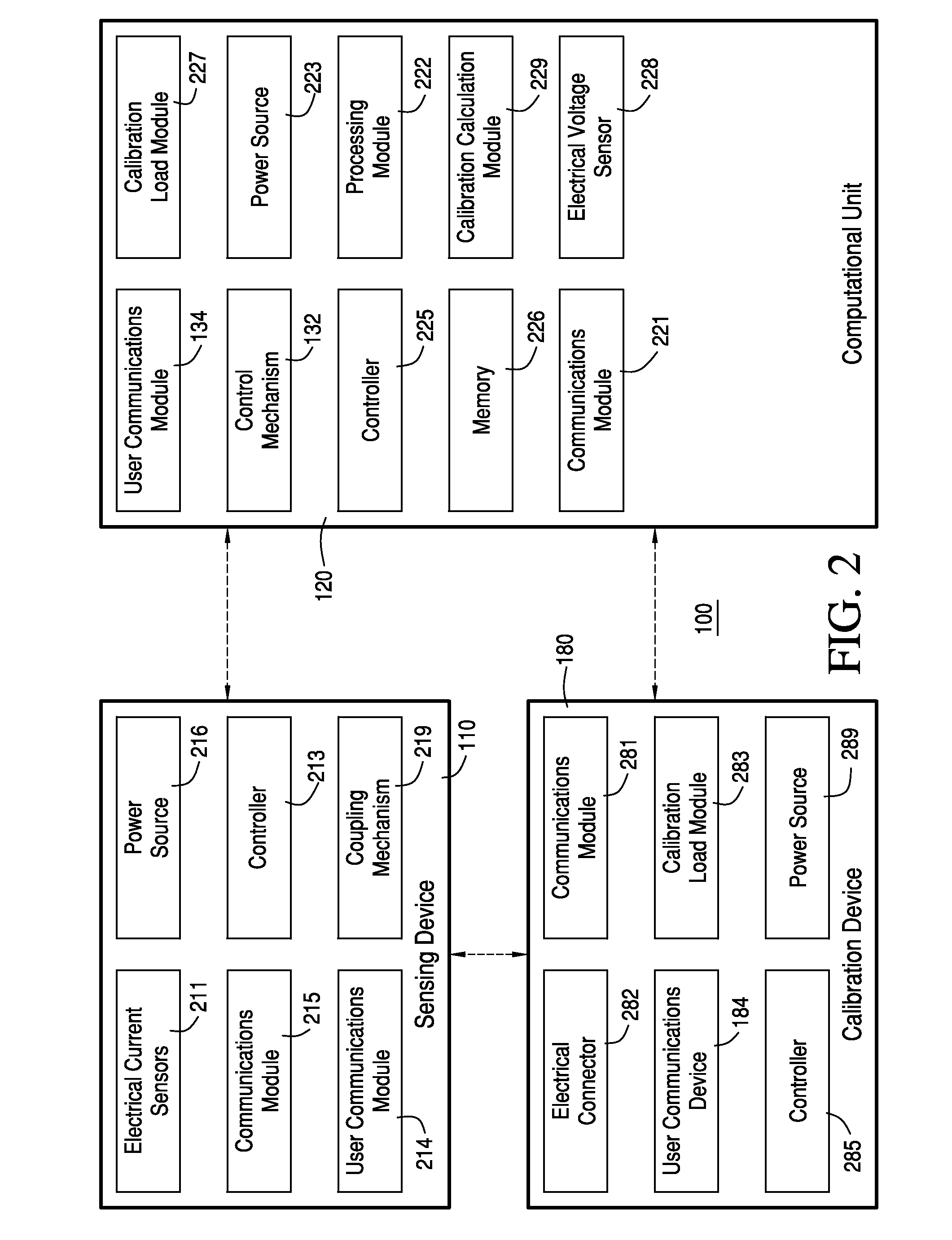
[0116]Specifically, FIG. 14 illustrates an example of switched load 1405, according to a Switched load 1405 can include: (a) switches 1187 and 1442; and (b) calibration loads 1188 and 1441. In this embodiment, switched load 1405 replaces switched load 1105 in calibration device 180 of FIGS. 2 and 11.

[0117]In this embodiment, switched load 1405 can be configured to calibrate the measurement of a single current carrying conductor (a feeder to the branch circuit labeled “Line”) being measured by sensing device 110. In this embodiment, controller 285 can switch between calibration loads 1188 and 1441 to provide two different sets of measurement to use in the calibration process. In other examples, switched load 1405 can include three or more switch of three or more calibration loads.

fourth embodiment

[0118]FIG. 15 illustrates an example of switched load 1505, according to a Switched load 1505 can include: (a) switches 1587 and 1542; and (b) calibration loads 1588 and 1541. In this embodiment, switched load 1505 replaces switched load 1105 in calibration device 180 of FIGS. 2 and 11.

[0119]In this embodiment, switched load 1505 can be designed to calibrate the measurement of two current carrying conductor (a feeder to the branch circuit labeled “Line 1” and “Line 2”) being measured by sensing device 110. In this embodiment, two distinct calibration loads 1588 and 1541 can be switched between individual line conductors and the neutral conductor under the control of a switching signal from controller 285. Controller 285 can control switching signals to electrically couple calibration loads as follows:

Calibration LoadsSwitch EnabledCoupledEffectSwitch 1587CalibrationPermit the calibration of ais enabledload 1541measurement of a feeder to abranch circuit labeled Line 1Switch 1542Cali...


PUM


Abstract

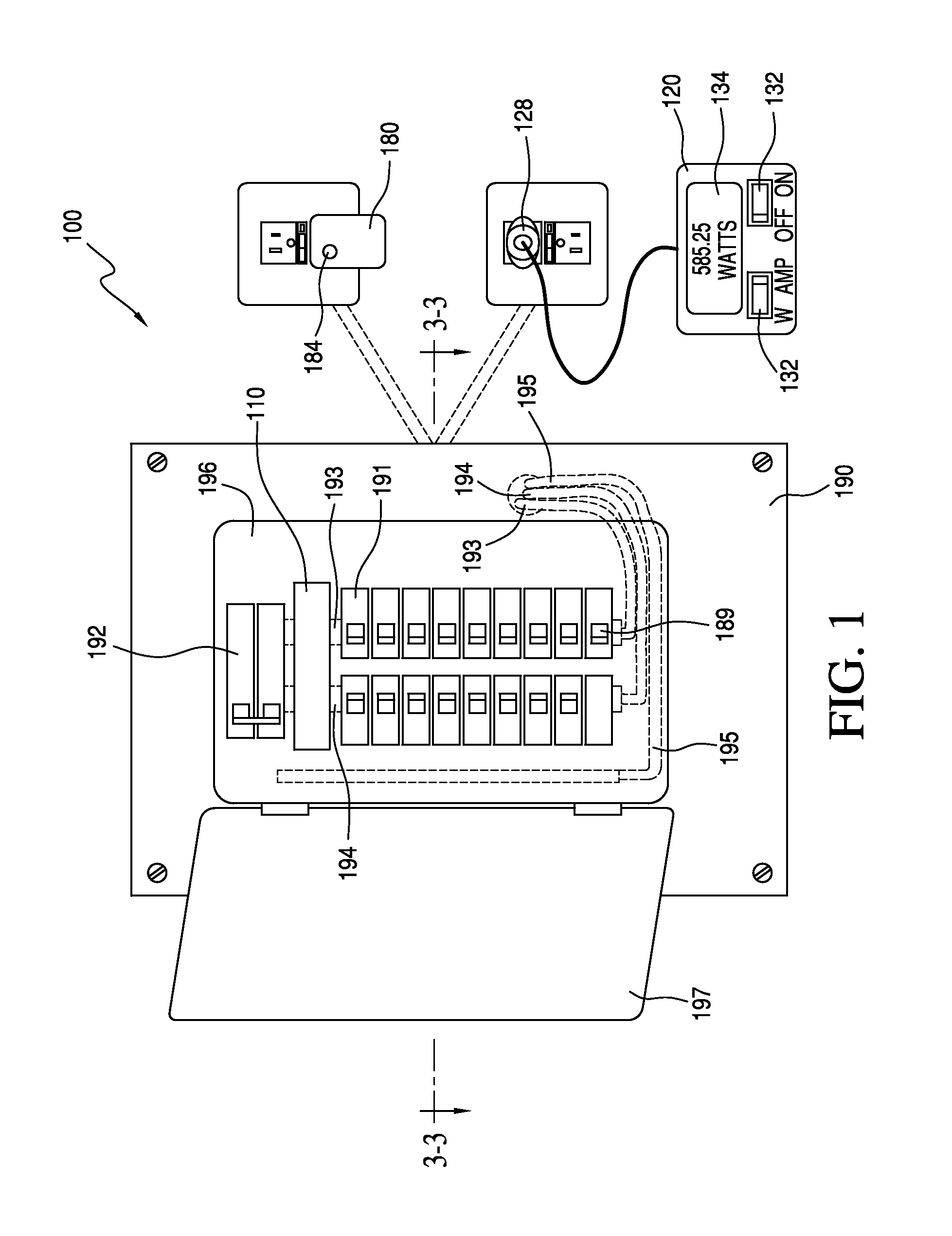
Some embodiments can concern a method of using a power consumption measurement device. The power consumption measurement device can be mechanically coupled to a surface of a circuit breaker box overlying at least part of one or more main electrical supply conductors for an electrical power infrastructure of a structure. The method can include: determining one or more first magnetic field readings from the one or more main electrical supply conductors using one or more sensors in the power consumption measurement device; after determining the one or more first magnetic field readings, electrically coupling a first calibration load to the electrical power infrastructure; while the first calibration load remains electrically coupled to the electrical power infrastructure, determining one or more second magnetic field readings from the one or more main electrical supply conductors using the one or more sensors in the power consumption measurement device; calibrating the power consumption measurement device using at least in part the one or more first magnetic field readings and the one or more second magnetic field readings, after calibrating the power consumption measurement device, determining one or more third magnetic field readings from the one or more main electrical supply conductors using the one or more sensors in the power consumption measurement device; and determining an electrical power used by the electrical power infrastructure of the structure using at least the one or more third magnetic field readings and the one or more calibration coefficients. Calibrating the power consumption measurement device can include determining one or more first calibration coefficients for the power consumption measurement device using at least in part the one or more first magnetic field readings and the one or more second magnetic field readings. Other embodiments are disclosed.

Description

CROSS-REFERENCE TO RELATED APPLICATIONS[0001]This application claims the benefit of U.S. Provisional Application No. 61 / 361,296, filed Jul. 2, 2010 and U.S. Provisional Application No. 61 / 380,174 filed Sep. 3, 2010. This application is also a continuation-in-part of U.S. application Ser. No. 12 / 567,561, filed Sep. 25, 2009. U.S. Provisional Application Nos. 61 / 361,296 and 61 / 380,174 and U.S. application Ser. No. 12 / 567,561 are incorporated herein by reference.FIELD OF THE INVENTION[0002]This invention relates generally to apparatuses, devices, systems, and methods for monitoring electrical power, and relates more particularly to such apparatuses, devices, systems, and methods that monitor electrical power in one or more main electrical power conductors at an electrical circuit breaker panel of a structure.DESCRIPTION OF THE BACKGROUND[0003]A structure (e.g., a home or a commercial building) can have one or more main electrical power conductors that supply the electrical power to ele...

Claims


Application Information

Patent Timeline
IPC IPC(8): G01R35/04
CPCG01R15/207G01R21/001G01R21/06G01R22/06G01R22/063G01R33/09G01R35/04G01R15/202G01R35/007G01R31/327G01R33/07G01R35/005G01R21/08G01R33/0035G01R11/32G01R19/00G01R1/20G01R19/0092
Inventor PATEL, SHWETAK N.GUPTA, SIDHANTREYNOLDS, MATTHEW S.YOGEESWARAN, KARTHIK
Owner BELKIN INT
Learn More