
System and method for self-powered communications networks

a communication network and self-powered technology, applied in the field of self-powered communications networks, can solve the problems of lack or unreliability of power and communications infrastructure, high cost of infrastructure for customers, and increase in demand for utility services worldwide, so as to reduce the cost of providing power, avoid data communications service interruptions, and expand power and data infrastructure.

Inactive Publication Date: 2013-10-08
RUTMAN SERGE
View PDF3 Cites 3 Cited by
  • Summary
  • Abstract
  • Description
  • Claims
  • Application Information

AI Technical Summary

Benefits of technology

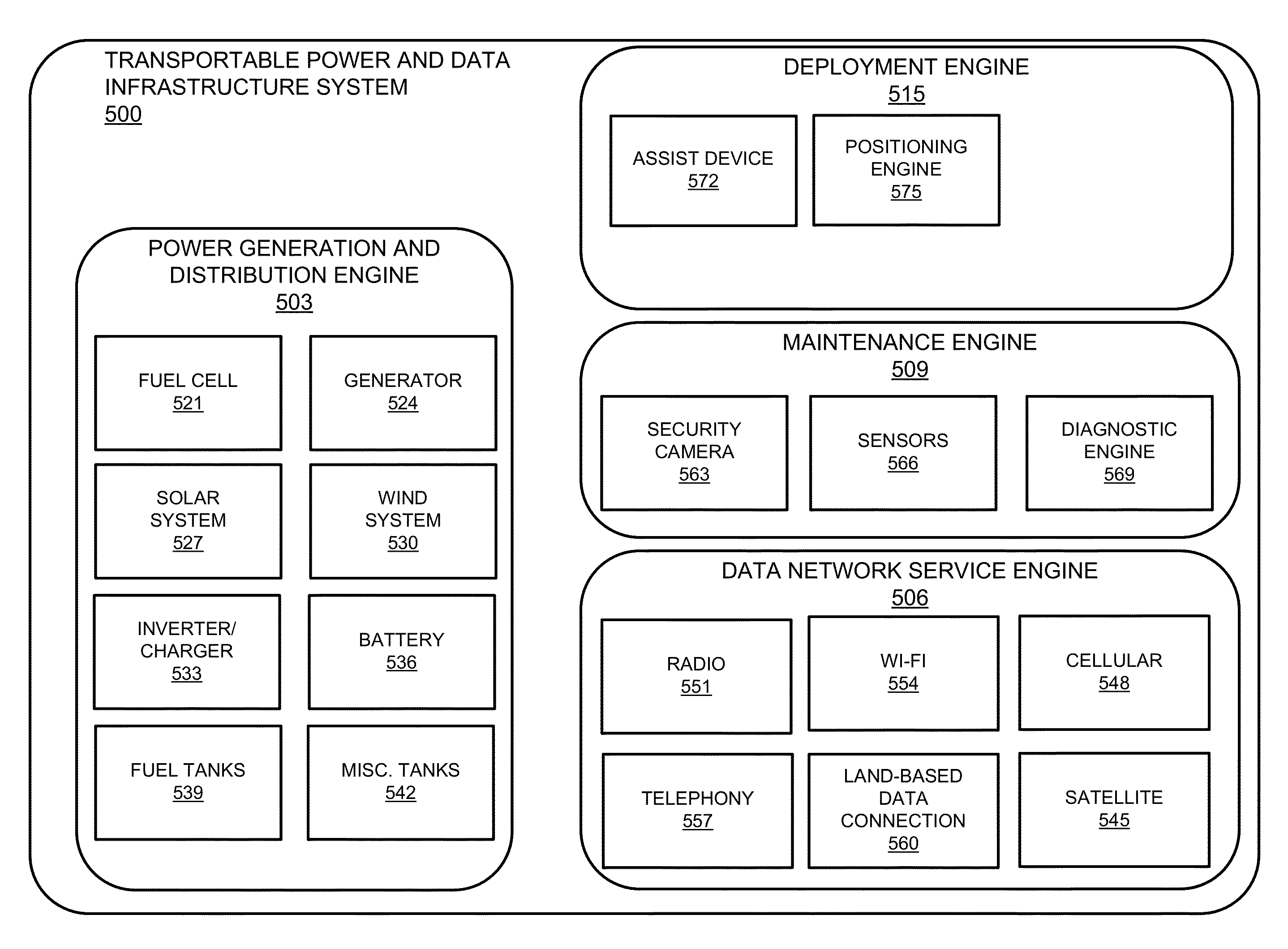
[0013]Techniques for providing localized power infrastructure and data infrastructure are disclosed. Some of the following advantages can be achieved using techniques described in this paper: (a) reaching utility customers regardless of whether utility company infrastructure (e.g., power carrying wires of a power company) can economically reach them; (b) reducing costs of providing power to a dwelling (e.g., house) not yet connected to the power grid; (c) generating power locally, thereby avoiding power service interruptions due to outages, whether attributed to damaged power transmission lines or power demand exceeding supply available on a power grid; (d) providing a data network connection locally, thereby avoiding data communications service interruptions due to data network outages or power outages, whether attributed to damaged power or communication lines, or to excess power or data network demand; (e) obviating the need for utility customers to maintain multiple commercial relationships to obtain power and data network connectivity; (f) assisting utility customers in meeting their clean energy generation mix requirements or goals; (g) expanding power and data infrastructure to geographic territories that do not have a “shared grid” wired distributions system; (h) fostering competition and enabling market competition in a local geographic area having deployed embodiments; (i) allowing for deployment in small increments, thereby avoiding massive capital outlays or years of environmental impact and zoning negotiations; and (j) providing more reliable power and data infrastructure in areas having weak power or data infrastructure or low development density.
[0026]Certain embodiments may be configured to utilize an external power grid, operated by a third party, concurrently with a power source of the power generation engine when providing generating and distributing power locally. By doing so, some such embodiments, can augment or replace the power provided by the external power grid the power generated by the power generation engine when necessary. For instance, in some embodiments, the maintenance engine of the transportable system is configured to detect intermittent power shortfalls on the external power grid operated by a third party power service provider, and control the power generation engine in order to compensate for the intermittent power shortfalls. Effectively, such embodiments can buffer power recipients / users from power outages or reductions.
[0029]In order to detect errors in the transportable system, for some embodiments, the maintenance engine is further configured to detect, from the internal operational condition or the external operational environment, an error in the data network service engine, the power generation engine, or the deployment engine, and alert a systems operator of the error. In other embodiments, the maintenance engine is capable of determining from the internal operational condition or the external operational environment that a current operation of the transportable system or a component thereof exceeds the damage risk threshold, and in response, alerting a systems operation of the excess. As described herein, the maintenance engine may also attempt to remedy an error detected in the transportable system or component thereof, or to adjust the transportable system or a component thereof to mitigate or eliminate a risk of damage.
[0030]In additional embodiments, the transportable system further comprises: a first transportable module comprising the maintenance engine, the data network service engine, the power generation engine, and the deployment engine; a second transportable module comprising a second maintenance engine, a second data network service engine, a second power generation engine, and a second deployment engine; an interconnect module that interconnects the first transportable module to the second transportable module; and wherein the first transportable module uses the second maintenance engine to augment or redundantly support the maintenance engine, the first transportable module uses the second data network service engine to augment or redundantly support the data network service engine, the first transportable module uses the second power generation engine to augment or redundantly support the power generation engine, or the first transportable module uses the second deployment engine to augment or redundantly support the deployment engine. By using two modules (i.e., a first transportable module and a second transportable module), certain embodiments can provide redundancy in the even that one of the modules partially or completely fails. For example, when the power generation engine of the first transportable module fails, the second power generation engine of the second transportable module can take over the failed engine's load, usually transparently. In another example, when the data network service engine of the first transportable module fails, the second data network service engine of the second transportable module can take over the failed engine's bandwidth, usually transparently.
[0038]In other embodiments, the service enlisted may be to protect the transportable system. In some embodiments, protecting the system may involve reacting to damage risk conditions such as incoming a hailstorm. A service may instruct the transportable system to open a hail umbrella to protect the solar panels. In other embodiments, the system may monitor for and alert the user or service upon detection of such damage risk conditions, thereby enabling the user or service to react by opening the hail umbrella (or other protective measure).

Problems solved by technology

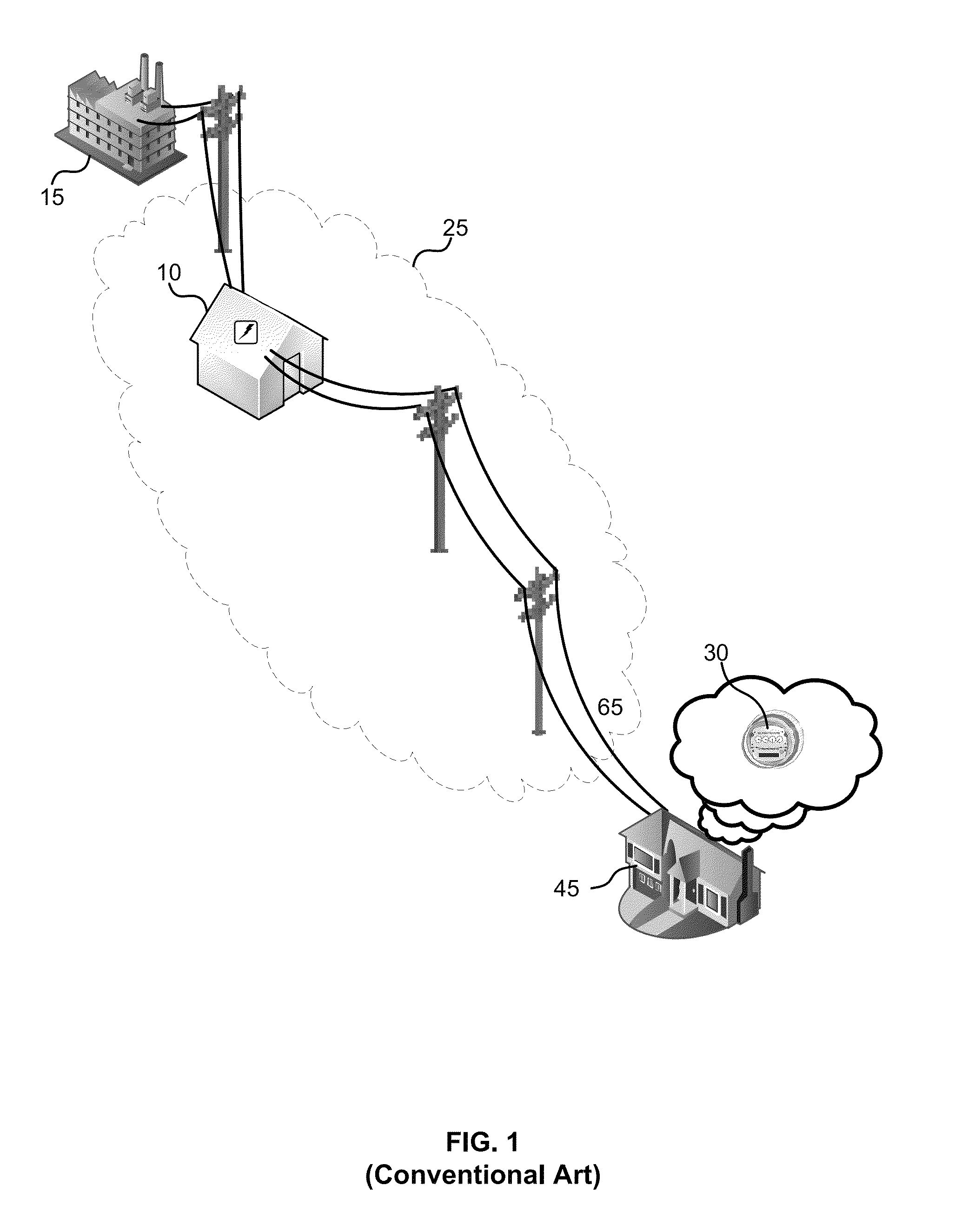
Of those parts of the world that have the benefit of power and communications infrastructure, such infrastructure may come at a high cost to its customers, or may not be as reliable as the power and communications services afforded to other, more developed areas of the world (e.g., metropolitan areas).
Several factors can be attributed to the lack or unreliability of power and communications infrastructure.
One factor causing unreliability is the general, worldwide increase in demand for utility services.
Increases in electricity demand are well known to result in rolling blackouts in order to keep up with consumer demand.
Other factors that can be attributed to the lack or unreliability of power and communications infrastructure include the breakdown of a stressed and aging infrastructure and the reluctance of utility companies (e.g., power companies, telecommunication companies) to invest in infrastructure or infrastructure upgrades in areas having little to no return on investment (e.g., high speed data network connections in rural areas).
Also troubling is the cost and waste associated with traditional forms of power and communications infrastructure.
The further the electricity has to travel to reach its intended users, the greater the power loss.
Such loss is correlated with wasted fuel used to generate the electricity and unnecessary pollution produced during power generation.
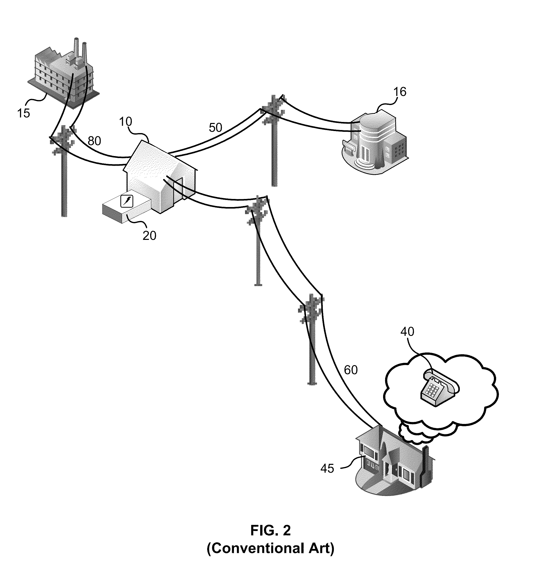
Other than the POTS provided by telephone companies, none of these providers supply the power needed to utilize the their services, leaving the consumer to rely on a power service provider.
Further, depending on the embodiment, the damage risk threshold may be a quantified level of risk of danger to the transportable system or a component thereof, at or after which the risk to the transportable system or the component is unacceptable without a change to the transportable system.

Method used


Image

  • System and method for self-powered communications networks
  • System and method for self-powered communications networks
  • System and method for self-powered communications networks

Examples


Embodiment Construction

[0059]In the description herein, a preferred embodiment of the invention is described, including preferred systems, methods, components, and process steps. After reading this application, those skilled in the art would realize that embodiments of the invention might be implemented using a variety of other components and techniques not specifically described, without undue experimentation or further invention, and that such other components and techniques would be within the scope and spirit of the invention.

[0060]Lexicography

[0061]The following terms relate or refer to aspects of the invention or its embodiments. The general meaning of each of these terms is intended to be illustrative.

[0062]The phrase “power infrastructure” describes an underlying framework and structure of a system for providing (also referred to as “delivering” or “transmitting”) power to consumers of the power (also referred to as “users”). For example, power infrastructure may include power transmission lines, ...


PUM


Abstract

Techniques for providing localized power infrastructure and data infrastructure are disclosed. A transportable system for providing localized power infrastructure and data infrastructure can include: a data network service engine configured to function as a local data network service provider; a power generation engine configured to function as a local power service provider that generates and distributes power locally; a deployment engine configured to assist in deploying one or more components of the transportable system; and a maintenance engine configured to maintain operation and security of the transportable system. In some embodiments, multiple transportable systems can be deployed and then centrally monitored or controlled as a single, utility system and / or a single data delivery infrastructure.

Description

CROSS-REFERENCE TO RELATED APPLICATION[0001]This application claims priority from U.S. Provisional patent application Ser. No. 61 / 350,807, entitled “Self-Powered Communication Network,” filed Jun. 2, 2010, which is incorporated by reference.DESCRIPTION OF THE RELATED ART[0002]In some areas of the world, there is an absence of power infrastructure (e.g., electric / power grids, power plants), communications infrastructure (e.g., Public Switched Telephone Network (PSTN), Digital Subscriber Line (DSL), Internet connectivity via cable), or both. Areas usually lacking such infrastructure include sparsely populated regions of the world, geographically remote locations of the world, and many regions of third world countries. Of those parts of the world that have the benefit of power and communications infrastructure, such infrastructure may come at a high cost to its customers, or may not be as reliable as the power and communications services afforded to other, more developed areas of the w...

Claims


Application Information

Patent Timeline
Patent Type & Authority Patents(United States)
IPC IPC(8): G05D3/12G06F17/00G06F19/00G06F11/30G01M17/00G01R21/06G05D5/00G05D9/00G05D11/00G05D17/00G05D1/00G06F7/00H04Q1/30G08B23/00G08B1/08G06F15/16G01R21/133G01R11/56G21C17/00
CPCB60L11/182H04L41/06H04L12/14Y02T90/16Y02T90/122Y02T90/14Y02T10/7005Y04S40/00Y02T10/70Y02T10/7072Y02T90/12
Inventor RUTMAN, SERGE
Owner RUTMAN SERGE
Learn More