Measuring system for ophthalmic surgery

a technology for ophthalmology and measuring system, applied in the field of measuring system for ophthalmology, can solve the problems of wavefront sensors, which are disclosed in documents, and the deviation of the exiting wavefront of the plane wavefront, and achieve the effect of increasing the working distan

Active Publication Date: 2012-03-22
CARL ZEISS MEDITEC AG
View PDF0 Cites 32 Cited by
  • Summary
  • Abstract
  • Description
  • Claims
  • Application Information

AI Technical Summary

Benefits of technology

The technical effect of this patent is to provide a device for inspecting objects with high precision through use of multiple optical assemblies. The device includes one or more sensors placed close enough to the object to capture detailed images without distortion caused by external factors like gravity or air currents. A specific embodiment involves a laser system used during ophthalmic surgeries to measure the position of the patient's cornea accurately. Another aspect relates to adjusting the spacing between the sensor(s) and the objective (the part of the machine responsible for collecting data about the object) within certain limits to ensure optimal performance.

Problems solved by technology

The present invention relates to a measuring system for ophthalmic surgery that uses a wavefront sensor and imaging optics. The technical problem addressed is the limited use of wavefront sensors in surgical operations due to the need for a short distance between the object and the optical component closest to the object. The invention aims to provide a measuring system with a wavefront sensor that is suitable for use in eye surgery, particularly cataract surgery, and that can inspect an object by analyzing wavefronts while measuring a three-dimensional structure data set.

Method used


Image

  • Measuring system for ophthalmic surgery
  • Measuring system for ophthalmic surgery
  • Measuring system for ophthalmic surgery

Examples


Embodiment Construction

[0089]In the exemplary embodiments described below, components that are alike in function and structure are designated as far as possible by alike reference numerals. Therefore, to understand the features of the individual components of a specific embodiment, the descriptions of other embodiments and of the summary of the invention should be referred to.

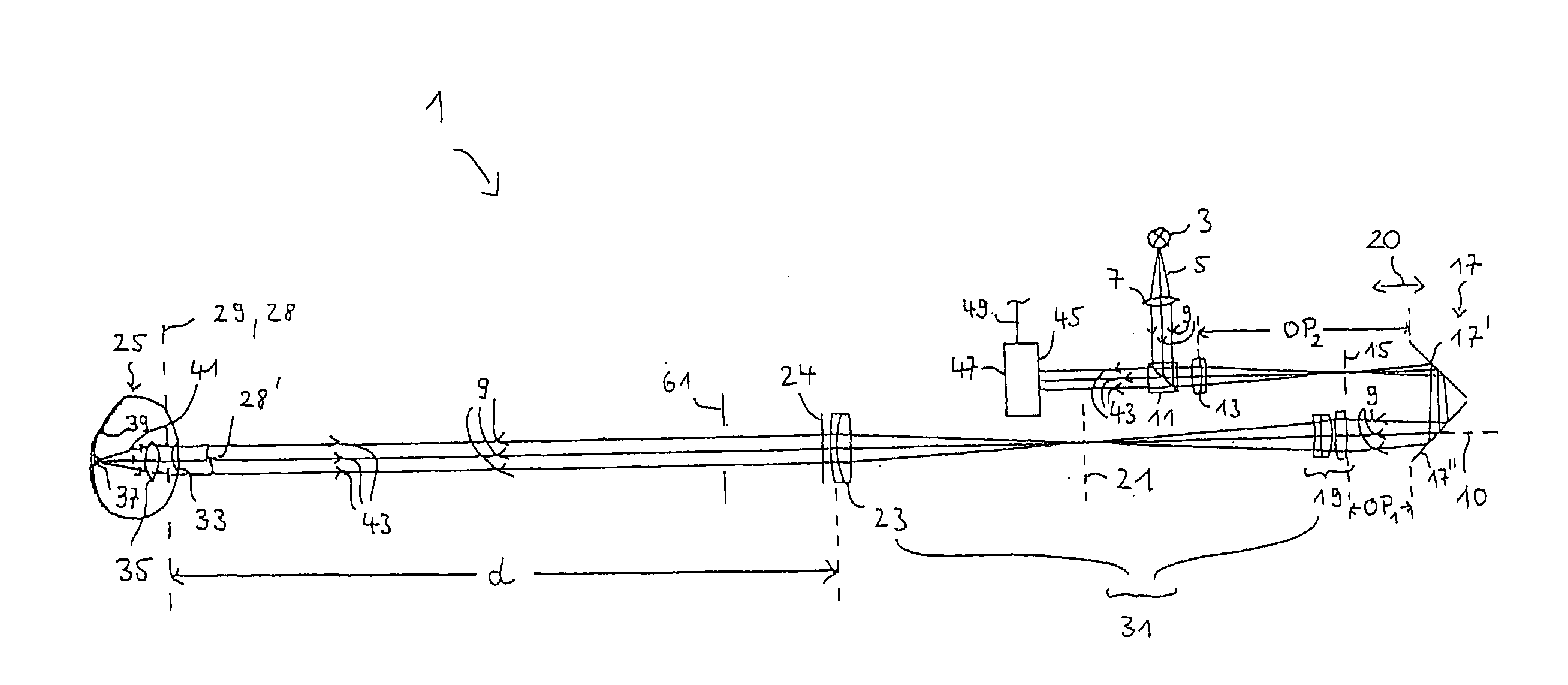
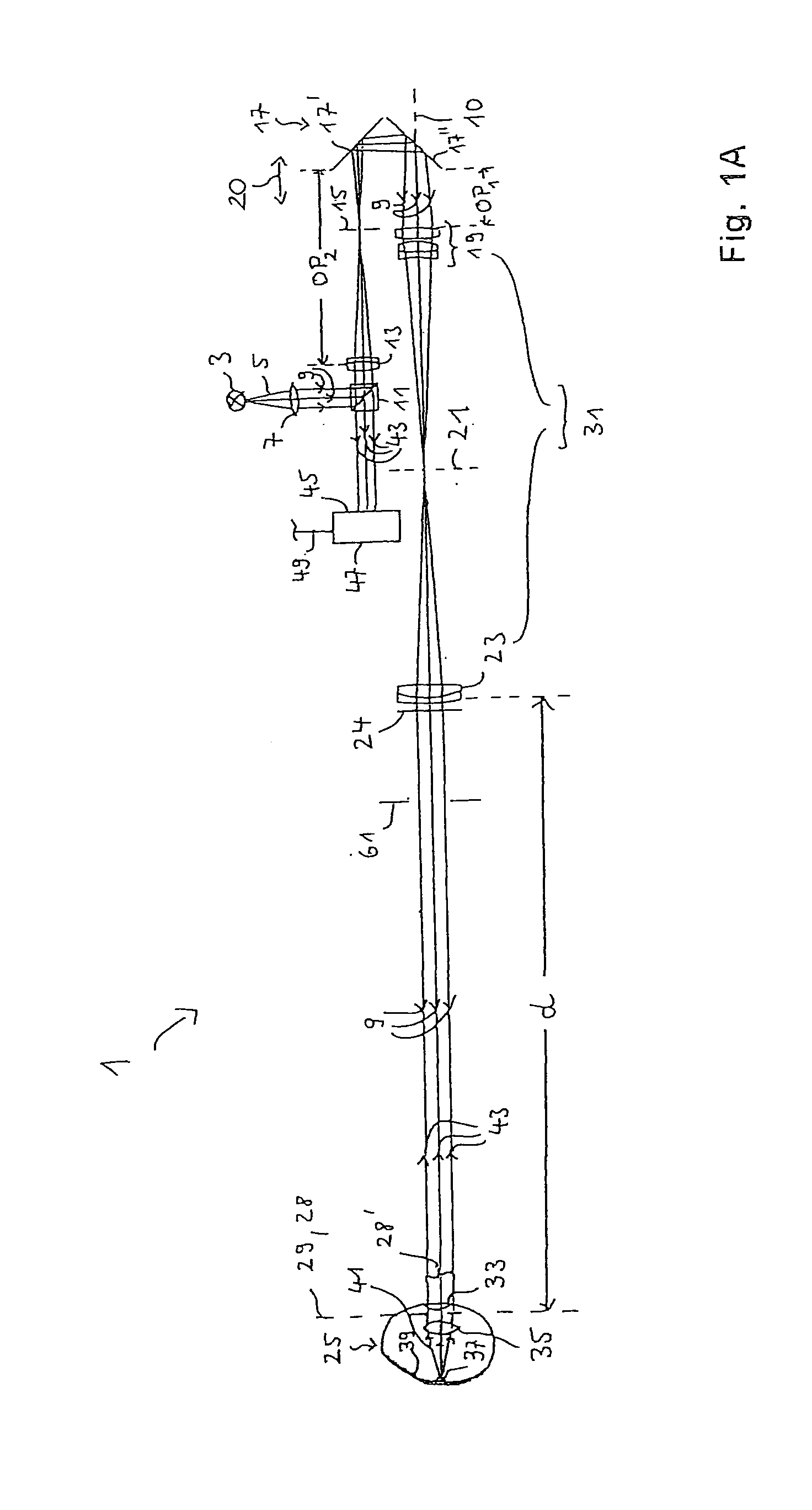
[0090]FIG. 1A schematically illustrates an optical measuring system 1 according to an embodiment. Measuring system 1 comprises a light source 3, which generates measuring light 5. Measuring light 5 is collimated by collimating optics 7 for generating measuring light 9, which substantially consists of plane wavefronts. Measuring light 9 is reflected at the beam splitter 11 and traverses cemented element 13. The measuring light, which is converged by cemented element 13 passes through aperture 15 and is deflected by 180° by reflector 17 which comprises two mirror surfaces 17′ and 17″, which are oriented orthogonal to each other. Thereb...


PUM


Abstract

The invention relates to an optical measuring system comprising a wave front sensor for characterizing a shape of a wave front of measuring light and an imaging lens, wherein the imaging lens comprises a first optical assembly and a second optical assembly for imaging an object region in an entrance region of the wave front sensor. A distance between the object region and the first optical assembly is larger than a focal length of the first optical assembly. Furthermore, the optical measuring system can comprise an optical microscopy system and optionally an OCT system for carrying out different optical examination methods at the same time.

Description


Claims


Application Information

Patent Timeline
Owner CARL ZEISS MEDITEC AG
Why Eureka
Try Eureka