
Method of manufacturing micro lens array

a micro lens and array technology, applied in the field of manufacturing a micro lens array, can solve the problems of affecting the image quality of the micro lens, beams may adversely affect the image obtained it is difficult to align the micro lens and the mask pattern where the focus is formed by the micro lens, so as to prevent the quality of the image

Active Publication Date: 2012-03-22
INHA UNIV RES & BUSINESS FOUNDATION
View PDF2 Cites 9 Cited by
  • Summary
  • Abstract
  • Description
  • Claims
  • Application Information

AI Technical Summary

Benefits of technology

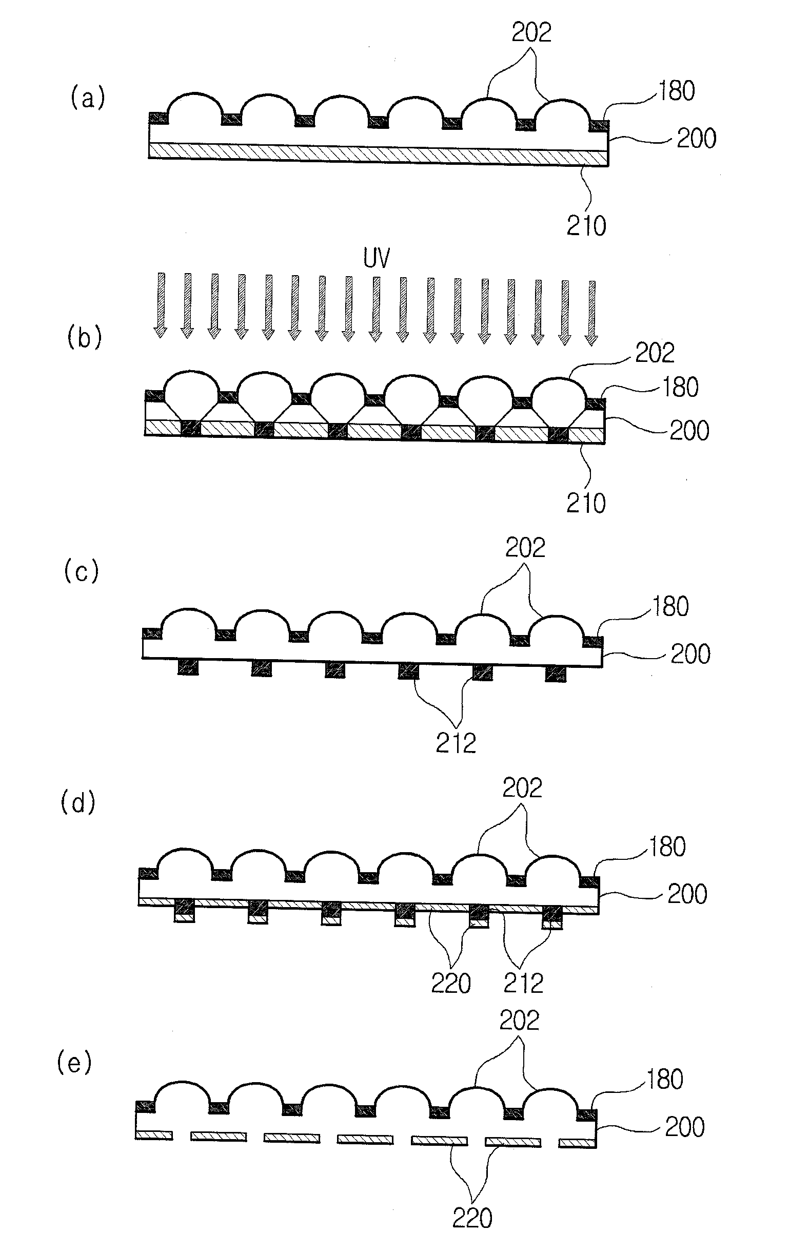
[0011]The present invention provides a method of manufacturing a micro lens array for preventing a quality of an image on a focal plane of a micro lens from deteriorating due to a beam on an off-axis surface, by forming a shading film preventing the beam from penetrating through a space between lenses in the micro lens array.
[0012]The present invention also provides a method of manufacturing a micro lens array, which can quickly manufacture a lens having a high numerical aperture or any shape, such as an aspheric shape, at a low cost.
[0013]The present invention also provides a method of manufacturing a micro lens array, where a micro lens and a mask pattern are easily aligned by forming the mask pattern at a focus region formed by a lens of the micro lens array.

Problems solved by technology

However, such methods require a model or a mask to form a micro lens, and it is difficult to quickly form micro lenses having a predetermined shape in a predetermined arrangement.
Thus, if a beam on an off-axis surface penetrated through the space is irradiated on a focus of the micro lenses, the beam may adversely affect an image obtained by the micro lenses.
Also, since the lenses of the micro lens array are very small, it is very difficult to align the micro lens and a mask pattern where a focus is formed by the micro lens.

Method used


Image

  • Method of manufacturing micro lens array
  • Method of manufacturing micro lens array
  • Method of manufacturing micro lens array

Examples


Embodiment Construction

[0029]Hereinafter, the present invention will be described more fully with reference to the accompanying drawings, in which exemplary embodiments of the invention are shown.

[0030]First, a lens manufacturing apparatus used to perform a method of manufacturing a micro lens, according to an embodiment of the present invention will be described.

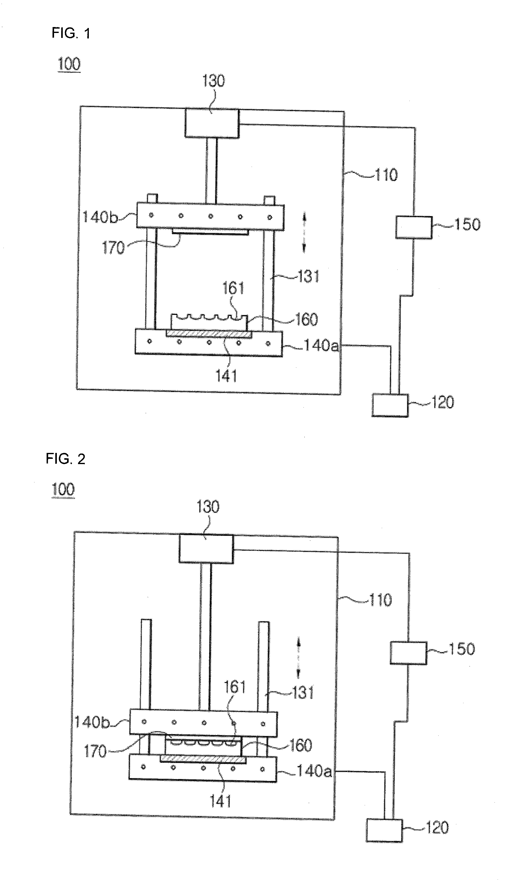
[0031]FIG. 1 is a diagram of a lens manufacturing apparatus for performing a method of manufacturing a micro lens, according to an embodiment of the present invention, and FIG. 2 is a diagram for describing an operation of the lens manufacturing apparatus 100 of FIG. 1.

[0032]Referring to FIGS. 1 and 2, the lens manufacturing apparatus 100 includes a vacuum chamber 110, a vacuum unit 120, an elevating cylinder 130, a lower frame 140a, an upper frame 140b, and a controller 150.

[0033]The vacuum chamber 110 provides a lens manufacturing space by forming a vacuum therein. The vacuum chamber 110 is selectively sealed according to a progress of operatio...


PUM

PropertyMeasurementUnit
Temperatureaaaaaaaaaa
Transparencyaaaaaaaaaa
Melting pointaaaaaaaaaa

Abstract

A method of manufacturing a micro lens array, wherein the quality of an image is prevented from being deteriorated as a beam on an off-axis surface reaches a focal plane of a micro lens by forming a shading film for preventing the beam from penetrating through a space between micro lenses of the micro lens array, a micro lens having a high numerical aperture or any shape, such as an aspheric shape, is quickly manufactured at a low cost, and the micro lenses and a mask pattern are easily aligned by forming a mask pattern on a focus region formed by the micro lenses of the micro lens array.

Description

CROSS-REFERENCE TO RELATED PATENT APPLICATION[0001]This application claims the benefit of Korean Patent Application Nos. 10-2010-0091849, filed on Sep. 17, 2010, 10-2010-0091850, filed on Sep. 17, 2010, and 10-2010-0099275, filed on Oct. 12, 2010, in the Korean Intellectual Property Office, the disclosure of which is incorporated herein in its entirety by reference.BACKGROUND OF THE INVENTION[0002]1. Field of the Invention[0003]The present invention relates to a method of manufacturing a micro lens array, and more particularly, to a method of manufacturing a micro lens array, which prevents a beam on an off-axis from reaching a focal plane of a micro lens, enables easy alignment of the micro lens and a pattern where a focus is formed, and can quickly manufacture a lens having any one of various shapes at a low cost.[0004]2. Description of the Related Art[0005]A micro lens is defined to have a diameter below or equal to 1 mm, but a lens having a diameter equal to or above 5 mm is som...

Claims


Application Information

Patent Timeline
IPC IPC(8): G03F7/20C08J7/04B29D11/00C08J7/043
CPCB29D11/00365G02B3/0031G03F7/0005C08J2369/00C08J2333/12C08J2367/02C08J7/047B29D11/00298C08J7/0427C08J7/043
Inventor LEE, HAN SUPPARK, BONG GUKJO, CHUL-JINCHOI, KI WOON
Owner INHA UNIV RES & BUSINESS FOUNDATION
Learn More